Our Products
See All Categories
Our company
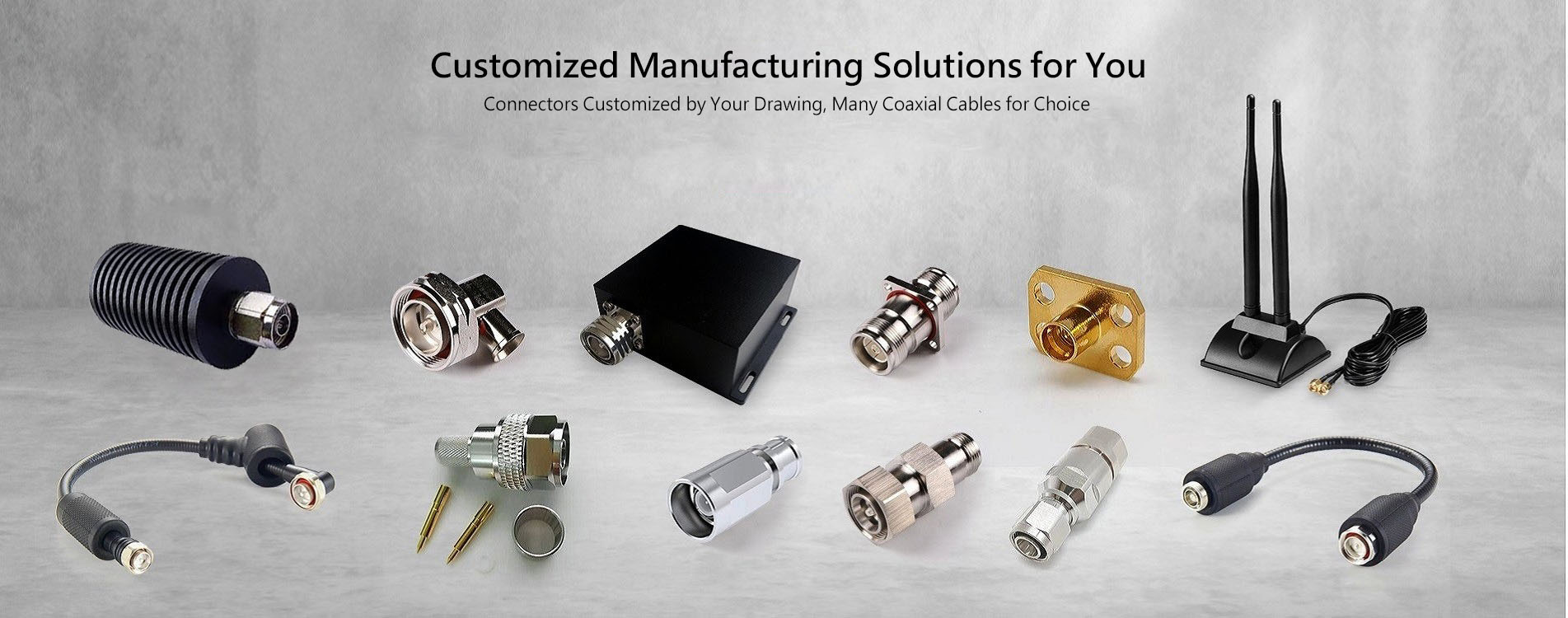
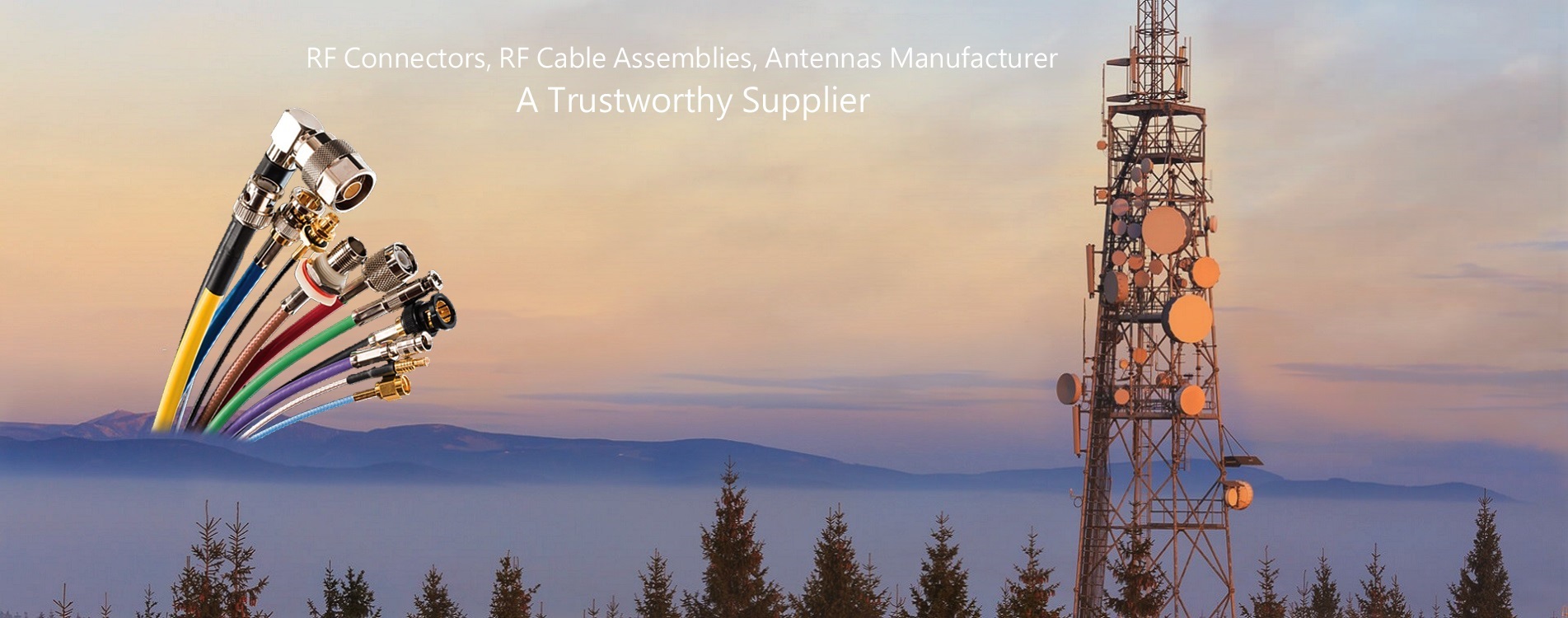
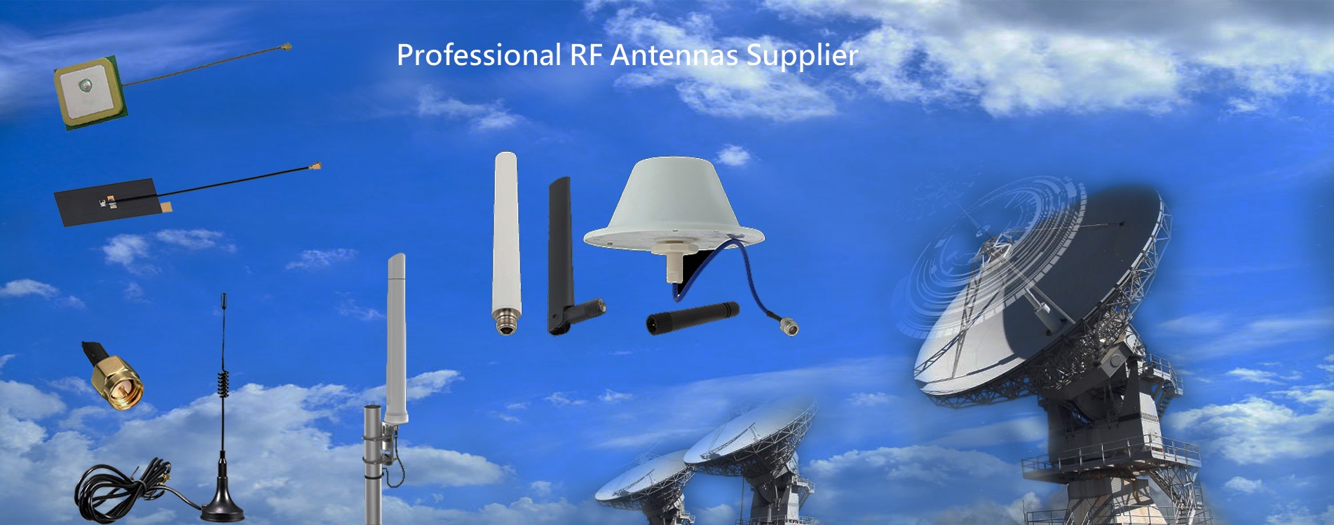
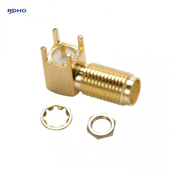
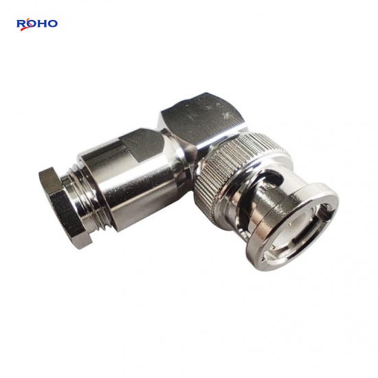
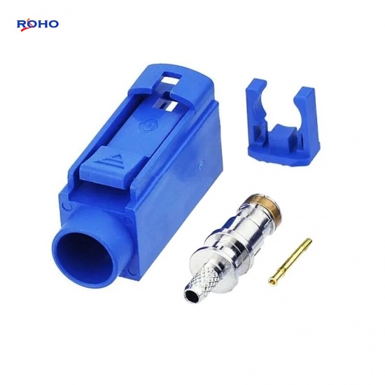
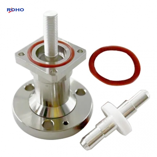
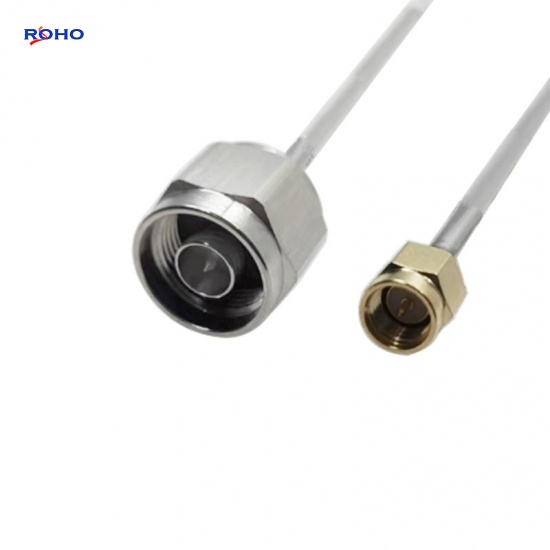
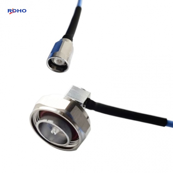
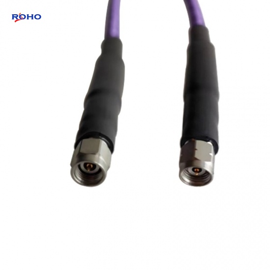
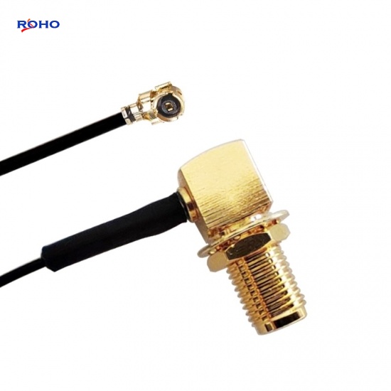
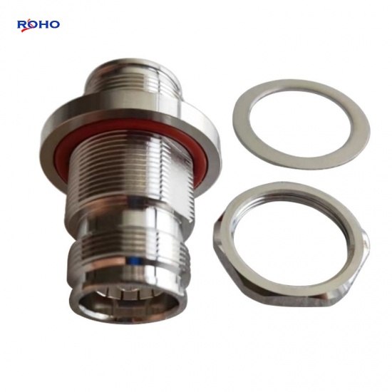
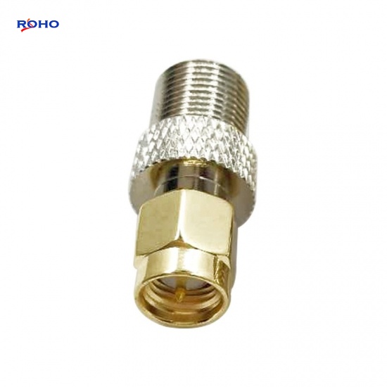
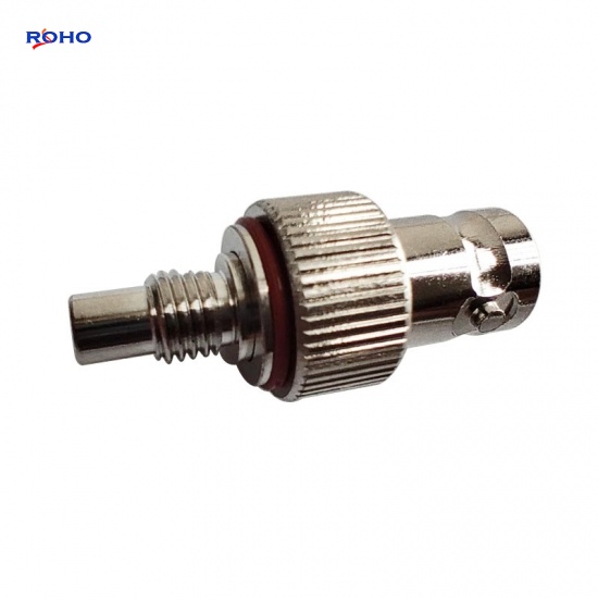
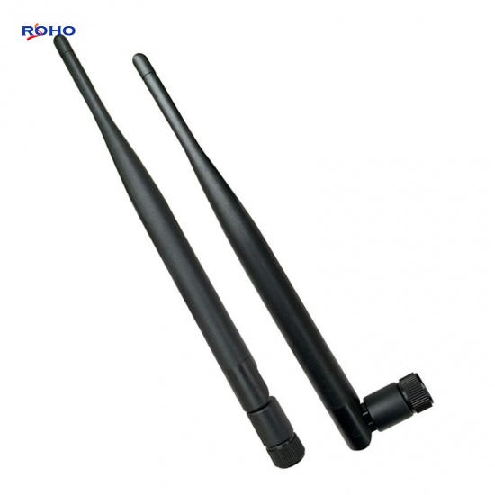
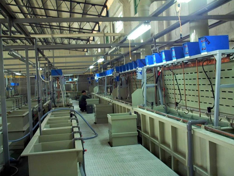
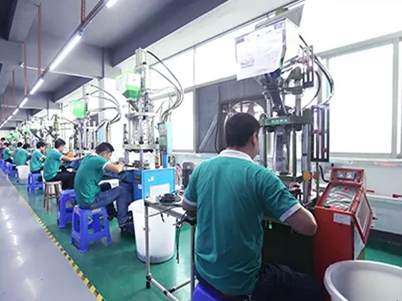
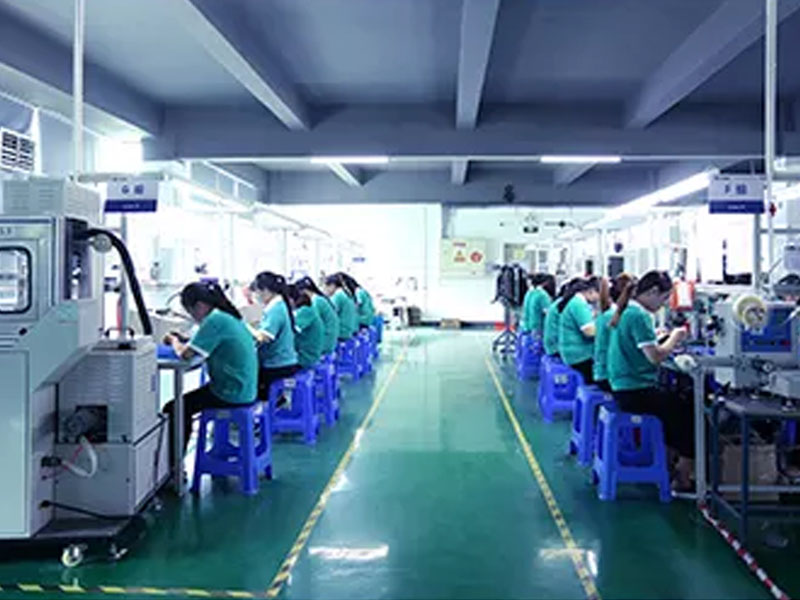
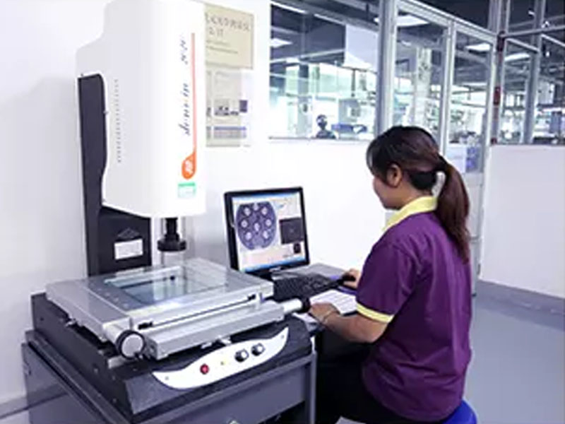
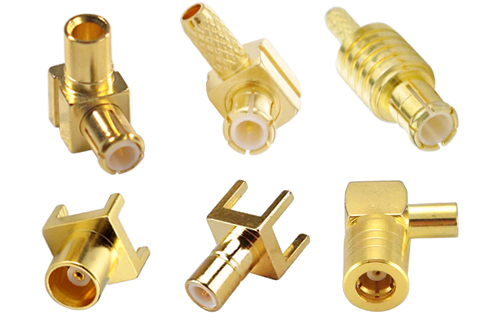
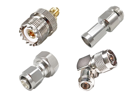
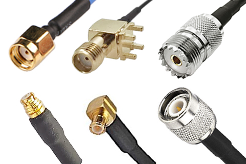
    ROHO Connector Limited is a well-known RF connectors, RF cable assemblies, RF antennas and RF&microwave components manufacturing enterprises, as a high-tech enterprise in China, ROHO design and production as one, with first-class design and engineering team, is a high-tech manufacturing enterprise.     ROHO offers a full range of RF connectors, including small MMCX, SMC, SMP, SSMA, SSMB, MCX, IPEX/ U.FL /MHF, etc., popular SMA, SMB, SMC, F type, etc. FAKRA, TNC, UHF, 1.0/2.3, 1.85mm, 2.4mm, 2.92mm, 3.5mm, BNC, and large 4.3/10,DIN 7/16, BNC, N type, QMA, QN, NEX10. They are built in male, female, plug, jack, receptacle or sexless gender, in 50ohm or 75ohm Impedance and in standard polarity, reverse polarity or reverse thread designs. as well as straight, radius right angle or right angle. they can be mounted with bulkhead, 2 hole panel or 4 hole panel configurations, Frequency up to 18GHz, 26.5GHz, 40GHz or 110GHz. these products are mainly used in communications, radio frequency identification, automotive, medical, aerospace, data storage, network signal transmission, military and other field.     ROHO also has extensive experience in the RF microwave industry, mainly engaged in RF modules of base stations, indoor distributed passive devices, customized development of RF modules of communication private networks, include RF attenuators, RF terminators (also called RF loads or dummy loads), power dividers (also known as RF power tappers or coaxial splitters) and RF antennas etc. Some members of our R&D team are members of the R&D team of the first 5.8GHz microwave sensor in China.     Excellent, innovative and professional services are our own mission. Our goal is higher speed, morereliability, and cost-effective connectivity solution. ROHO promises to customers around the world with the best quality, cost-effective products and services!
More About
Latest News
  • 20

    Jun 2026

    RF Cable Assemblies: The Critical Link in High-Performance Signal Transmission
        In the intricate world of radio frequency (RF) and microwave systems, the cable assembly is often the unsung hero—or the silent saboteur. While amplifiers, filters, and antennas receive considerable attention, the interconnecting cable assemblies are the vital links that can either preserve signal integrity or introduce losses, reflections, and interference that degrade system performance. As wireless networks push toward higher frequencies, data rates, and power levels, the demands on RF cable assemblies have intensified, making their selection a critical engineering decision.     This report provides a comprehensive overview of the classification and key performance characteristics of RF cable assemblies, offering essential guidance for engineers, system integrators, and procurement professionals.     An RF cable assembly is a complete transmission line unit comprising a coaxial cable with connectors terminated at one or both ends. It is designed to transmit RF signals from one point to another while maintaining the system's characteristic impedance, minimizing signal loss, and preventing interference. Cable assemblies are used across virtually every RF application: telecommunications infrastructure, test and measurement, aerospace and defense, broadcast, medical devices, and consumer electronics.     The simplest assembly consists of: Inner Conductor: Carries the RF signal (solid or stranded wire). Dielectric Insulator: Separates the inner conductor from the outer shield while maintaining constant impedance. Outer Conductor (Shield): Provides return path and electromagnetic shielding (braid, foil, or solid tube). Jacket: Protects the cable from environmental damage (mechanical, chemical, thermal). Connectors: Terminate the cable to interface with equipment (SMA, N-Type, BNC, TNC, 7/16 DIN, 4.3-10, etc.).     RF cable assemblies can be classified according to cable type, connector type, frequency range, power handling, and construction.     The cable itself is the defining component of the assembly. Cables are classified by their construction, dielectric material, and intended application.     Flexible Cables Construction: Braided outer conductor; stranded or solid inner conductor; flexible dielectric (often PTFE, FEP, or polyethylene). Characteristics: Easy to route and install; moderate loss; good flexibility; lower cost. Applications: General-purpose RF connections, test leads, jumpers, patch cables. Typical Frequency: Up to 18 GHz (some to 40 GHz). Example: RG-58, RG-316, LMR-400, RG-174.     Semi-Rigid Cables Construction: Solid copper or aluminum outer conductor; solid dielectric (PTFE); solid or stranded inner conductor. Characteristics: Excellent shielding (> 100 dB); very low loss; high phase stability; high power handling; minimal flexibility (can be bent once with special tools). Applications: High-frequency test equipment, military systems, ...
    Read More
  • 27

    May 2026

    CATV Splitters: The Unseen Backbone of Modern Broadband and Video Distribution
        In the era of gigabit broadband, streaming video, and smart home connectivity, one humble component quietly enables the entire cable television and data infrastructure: the CATV splitter. Often overlooked by consumers yet essential to network performance, these passive devices are responsible for distributing high‑frequency signals from a single cable drop to multiple outlets, set‑top boxes, cable modems, and other customer premises equipment. As operators upgrade networks to support DOCSIS 3.1, 4.0, and beyond, the demands on CATV splitters have never been greater.     This report examines the classification and key performance characteristics of CATV splitters, providing technical insights for network engineers, installers, and system integrators.     A CATV (Community Antenna Television) splitter is a passive RF device that takes one input signal (typically from a cable provider’s drop or a distribution amplifier) and divides it into two or more output signals, each carrying the same frequency content but at reduced power. Splitters are the fundamental building blocks of coaxial home and business networks, enabling multiple TVs, modems, and other devices to share a single cable connection.     CATV splitters are designed for 75‑ohm impedance, the standard for video, broadband, and satellite systems, and typically operate over a frequency range extending from 5 MHz to 1002 MHz, 1218 MHz, 1670 MHz, or even 3 GHz for next‑generation networks. Modern splitters must support bidirectional communication: downstream (from the network to the subscriber) and upstream (from the subscriber’s cable modem back to the network).     CATV splitters are classified by port configuration, frequency range, insertion loss, isolation, and environmental design.     The number of output ports is the most obvious classification, ranging from simple 2‑way splits to complex 8‑way or 16‑way distribution hubs. Port Count Typical Applications Theoretical Split Loss 2‑way Basic residential splits (e.g., feeding a modem and one TV) 3.0 dB 3‑way Uneven distribution (often one low‑loss port + two higher‑loss ports) 4.8 dB (equal split) 4‑way Multiple rooms, small businesses 6.0 dB 6‑way Larger residences, small MDUs (multi‑dwelling units) 7.8 dB 8‑way Apartment buildings, commercial installations 9.0 dB 16‑way Head‑end distribution, large MDUs 12.0 dB     Unequal (Tapped) Splitters: Some 3‑way and 4‑way splitters are designed with one "through" port having lower loss (e.g., 3.5 dB) and two or three "tap" ports with higher loss (e.g., 7 dB). This allows a cable modem to be connected to the low‑loss port while TV set‑top boxes use the higher‑loss ports, preserving signal quality for the most critical device.     As cable networks evolve, splitter bandwidth has expanded significantly. Legacy (5–860 MHz): Supports analog TV and early digital cable. Standard (5–1002 MHz): Cove...
    Read More
  • 06

    May 2026

    7/16 DIN Power Splitters: The High-Power Workhorses of Mission-Critical RF Infrastructure
        In the world of high-power RF distribution, where reliability, low passive intermodulation (PIM), and mechanical robustness are non-negotiable, the 7/16 DIN power splitter remains an indispensable component. Despite the growing popularity of more compact interfaces like 4.3-10, the 7/16 DIN connector—with its large contact area, superior power handling, and proven field history—continues to dominate macro-cell base stations, high-power broadcast transmitters, radar systems, and industrial RF heating applications.     This news report provides a comprehensive overview of the classification and key performance characteristics of 7/16 DIN power splitters, offering essential guidance for engineers and system integrators working in demanding RF environments.     The 7/16 DIN connector (also known as the 7/16 or 7-16 DIN) derives its name from the dimensions of its inner conductor (7 mm) and outer conductor (16 mm). Developed decades ago for high-power telecommunications, it has become the de facto standard for cellular base station interconnections across Europe and much of the world. Key attributes of the interface include: High power handling: Capable of carrying average power up to several hundred watts (and peak power into the kilowatts) due to the large contact surface area. Excellent low-PIM performance: The robust, high‑pressure contact interface inherently generates very low passive intermodulation, typically –160 dBc or better. Superior mechanical strength: Threaded coupling with a large nut provides a secure, weather‑resistant connection rated for 500+ mating cycles. Standardized impedance: 50 Ω, matching most communication and broadcast systems. Frequency range: Typically DC to 6 GHz, with precision designs usable to 7.5 GHz or even 11 GHz for specialized applications.     A 7/16 DIN power splitter is a passive device that divides a single RF input into two or more outputs while maintaining matched impedance and high isolation between ports. These splitters are the backbone of signal distribution in macro cells, DAS head‑ends, broadcast transmitters, and test laboratories that handle significant power levels.     7/16 DIN power splitters are classified according to circuit topology, port configuration, power rating, frequency coverage, and PIM performance grade.     Wilkinson Power Splitters     The Wilkinson topology is the industry standard for 7/16 DIN splitters used in infrastructure and broadcast. Named after its inventor, the Wilkinson splitter uses quarter-wave transmission lines and internal isolation resistors to achieve excellent performance. Low insertion loss: Excess loss typically 0.1–0.3 dB above theoretical split loss. High isolation: 20–30 dB between output ports, critical for preventing interference. Excellent VSWR: Typically 1.15:1 to 1.25:1 across the operating band. Low-PIM...
    Read More
Any question? Contact us now !

Leave A Message

Leave A Message
If you have questions or suggestions,please leave us a message,we will reply you as soon as we can!

Home

Products

skype

whatsapp