News
  • RF Cable Assemblies: The Critical Link in High-Performance Signal Transmission
    RF Cable Assemblies: The Critical Link in High-Performance Signal Transmission Apr 07, 2025
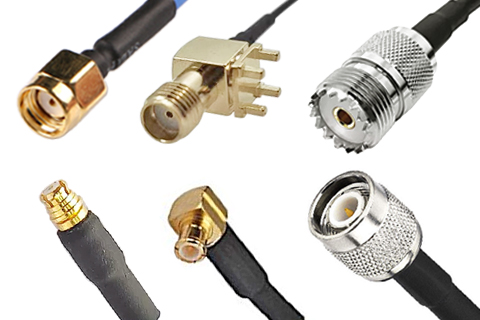
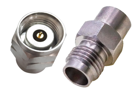
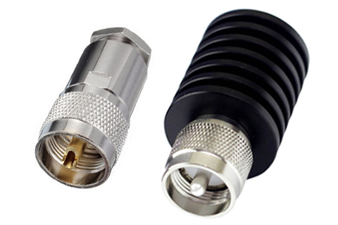
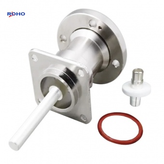
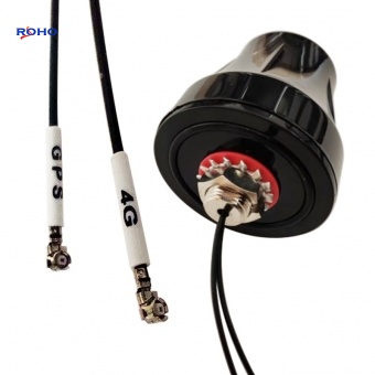
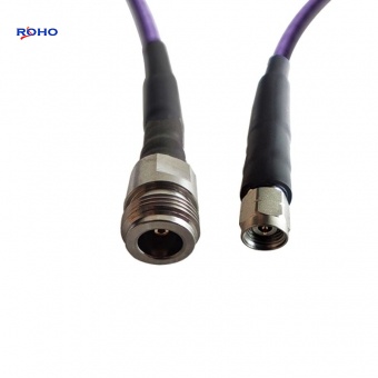
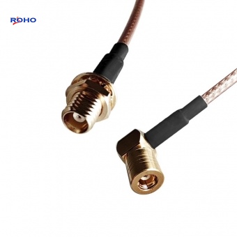
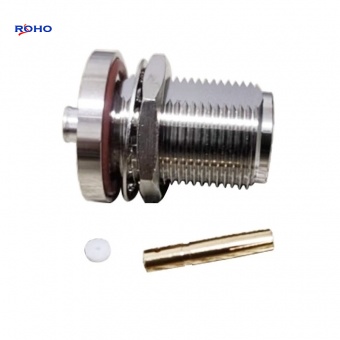
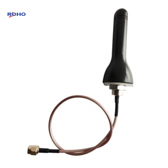
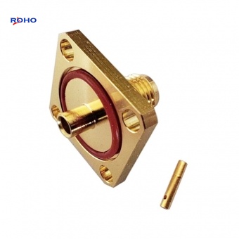
        In the intricate world of radio frequency (RF) and microwave systems, the cable assembly is often the unsung hero—or the silent saboteur. While amplifiers, filters, and antennas receive considerable attention, the interconnecting cable assemblies are the vital links that can either preserve signal integrity or introduce losses, reflections, and interference that degrade system performance. As wireless networks push toward higher frequencies, data rates, and power levels, the demands on RF cable assemblies have intensified, making their selection a critical engineering decision.     This report provides a comprehensive overview of the classification and key performance characteristics of RF cable assemblies, offering essential guidance for engineers, system integrators, and procurement professionals.     An RF cable assembly is a complete transmission line unit comprising a coaxial cable with connectors terminated at one or both ends. It is designed to transmit RF signals from one point to another while maintaining the system's characteristic impedance, minimizing signal loss, and preventing interference. Cable assemblies are used across virtually every RF application: telecommunications infrastructure, test and measurement, aerospace and defense, broadcast, medical devices, and consumer electronics.     The simplest assembly consists of: Inner Conductor: Carries the RF signal (solid or stranded wire). Dielectric Insulator: Separates the inner conductor from the outer shield while maintaining constant impedance. Outer Conductor (Shield): Provides return path and electromagnetic shielding (braid, foil, or solid tube). Jacket: Protects the cable from environmental damage (mechanical, chemical, thermal). Connectors: Terminate the cable to interface with equipment (SMA, N-Type, BNC, TNC, 7/16 DIN, 4.3-10, etc.).     RF cable assemblies can be classified according to cable type, connector type, frequency range, power handling, and construction.     The cable itself is the defining component of the assembly. Cables are classified by their construction, dielectric material, and intended application.     Flexible Cables Construction: Braided outer conductor; stranded or solid inner conductor; flexible dielectric (often PTFE, FEP, or polyethylene). Characteristics: Easy to route and install; moderate loss; good flexibility; lower cost. Applications: General-purpose RF connections, test leads, jumpers, patch cables. Typical Frequency: Up to 18 GHz (some to 40 GHz). Example: RG-58, RG-316, LMR-400, RG-174.     Semi-Rigid Cables Construction: Solid copper or aluminum outer conductor; solid dielectric (PTFE); solid or stranded inner conductor. Characteristics: Excellent shielding (> 100 dB); very low loss; high phase stability; high power handling; minimal flexibility (can be bent once with special tools). Applications: High-frequency test equipment, military systems, ...
    View details
  • CATV Splitters: The Unseen Backbone of Modern Broadband and Video Distribution
    CATV Splitters: The Unseen Backbone of Modern Broadband and Video Distribution Mar 03, 2025
        In the era of gigabit broadband, streaming video, and smart home connectivity, one humble component quietly enables the entire cable television and data infrastructure: the CATV splitter. Often overlooked by consumers yet essential to network performance, these passive devices are responsible for distributing high‑frequency signals from a single cable drop to multiple outlets, set‑top boxes, cable modems, and other customer premises equipment. As operators upgrade networks to support DOCSIS 3.1, 4.0, and beyond, the demands on CATV splitters have never been greater.     This report examines the classification and key performance characteristics of CATV splitters, providing technical insights for network engineers, installers, and system integrators.     A CATV (Community Antenna Television) splitter is a passive RF device that takes one input signal (typically from a cable provider’s drop or a distribution amplifier) and divides it into two or more output signals, each carrying the same frequency content but at reduced power. Splitters are the fundamental building blocks of coaxial home and business networks, enabling multiple TVs, modems, and other devices to share a single cable connection.     CATV splitters are designed for 75‑ohm impedance, the standard for video, broadband, and satellite systems, and typically operate over a frequency range extending from 5 MHz to 1002 MHz, 1218 MHz, 1670 MHz, or even 3 GHz for next‑generation networks. Modern splitters must support bidirectional communication: downstream (from the network to the subscriber) and upstream (from the subscriber’s cable modem back to the network).     CATV splitters are classified by port configuration, frequency range, insertion loss, isolation, and environmental design.     The number of output ports is the most obvious classification, ranging from simple 2‑way splits to complex 8‑way or 16‑way distribution hubs. Port Count Typical Applications Theoretical Split Loss 2‑way Basic residential splits (e.g., feeding a modem and one TV) 3.0 dB 3‑way Uneven distribution (often one low‑loss port + two higher‑loss ports) 4.8 dB (equal split) 4‑way Multiple rooms, small businesses 6.0 dB 6‑way Larger residences, small MDUs (multi‑dwelling units) 7.8 dB 8‑way Apartment buildings, commercial installations 9.0 dB 16‑way Head‑end distribution, large MDUs 12.0 dB     Unequal (Tapped) Splitters: Some 3‑way and 4‑way splitters are designed with one "through" port having lower loss (e.g., 3.5 dB) and two or three "tap" ports with higher loss (e.g., 7 dB). This allows a cable modem to be connected to the low‑loss port while TV set‑top boxes use the higher‑loss ports, preserving signal quality for the most critical device.     As cable networks evolve, splitter bandwidth has expanded significantly. Legacy (5–860 MHz): Supports analog TV and early digital cable. Standard (5–1002 MHz): Cove...
    View details
  • 7/16 DIN Power Splitters: The High-Power Workhorses of Mission-Critical RF Infrastructure
    7/16 DIN Power Splitters: The High-Power Workhorses of Mission-Critical RF Infrastructure Feb 10, 2025
        In the world of high-power RF distribution, where reliability, low passive intermodulation (PIM), and mechanical robustness are non-negotiable, the 7/16 DIN power splitter remains an indispensable component. Despite the growing popularity of more compact interfaces like 4.3-10, the 7/16 DIN connector—with its large contact area, superior power handling, and proven field history—continues to dominate macro-cell base stations, high-power broadcast transmitters, radar systems, and industrial RF heating applications.     This news report provides a comprehensive overview of the classification and key performance characteristics of 7/16 DIN power splitters, offering essential guidance for engineers and system integrators working in demanding RF environments.     The 7/16 DIN connector (also known as the 7/16 or 7-16 DIN) derives its name from the dimensions of its inner conductor (7 mm) and outer conductor (16 mm). Developed decades ago for high-power telecommunications, it has become the de facto standard for cellular base station interconnections across Europe and much of the world. Key attributes of the interface include: High power handling: Capable of carrying average power up to several hundred watts (and peak power into the kilowatts) due to the large contact surface area. Excellent low-PIM performance: The robust, high‑pressure contact interface inherently generates very low passive intermodulation, typically –160 dBc or better. Superior mechanical strength: Threaded coupling with a large nut provides a secure, weather‑resistant connection rated for 500+ mating cycles. Standardized impedance: 50 Ω, matching most communication and broadcast systems. Frequency range: Typically DC to 6 GHz, with precision designs usable to 7.5 GHz or even 11 GHz for specialized applications.     A 7/16 DIN power splitter is a passive device that divides a single RF input into two or more outputs while maintaining matched impedance and high isolation between ports. These splitters are the backbone of signal distribution in macro cells, DAS head‑ends, broadcast transmitters, and test laboratories that handle significant power levels.     7/16 DIN power splitters are classified according to circuit topology, port configuration, power rating, frequency coverage, and PIM performance grade.     Wilkinson Power Splitters     The Wilkinson topology is the industry standard for 7/16 DIN splitters used in infrastructure and broadcast. Named after its inventor, the Wilkinson splitter uses quarter-wave transmission lines and internal isolation resistors to achieve excellent performance. Low insertion loss: Excess loss typically 0.1–0.3 dB above theoretical split loss. High isolation: 20–30 dB between output ports, critical for preventing interference. Excellent VSWR: Typically 1.15:1 to 1.25:1 across the operating band. Low-PIM...
    View details
  • SMA Power Splitters: Enabling Precision Signal Distribution in Modern RF Systems
    SMA Power Splitters: Enabling Precision Signal Distribution in Modern RF Systems Jan 06, 2025
        As wireless networks evolve toward higher frequencies and greater complexity, the demand for compact, high-performance signal distribution components has never been more critical. Among these, SMA power splitters—also known as power dividers—have emerged as indispensable tools for engineers working in telecommunications, aerospace, defense, and test instrumentation. Leveraging the robust SubMiniature version SMA connector interface, these passive devices split a single RF input signal into multiple outputs with minimal loss, excellent isolation, and precise amplitude and phase matching.     This news report examines the classification and key performance characteristics of SMA power splitters, providing industry professionals with essential insights for component selection in demanding RF environments.     SMA power splitters are categorized primarily by their internal circuit topology, port configuration, power handling capability, and impedance. Each classification directly influences the device's electrical performance and suitability for specific applications.     Wilkinson Power Splitters     The Wilkinson design is the industry standard for applications requiring low insertion loss and high isolation between output ports. These splitters utilize quarter-wave transmission line sections and internal isolation resistors to achieve excellent performance over multi-octave bandwidths. A Wilkinson splitter ensures that each output port remains impedance-matched and that signals from different outputs do not interfere with one another.     Key characteristics of Wilkinson splitters include: Low insertion loss (excess loss typically 0.1–0.5 dB above the theoretical split loss) High isolation (typically 20–30 dB between output ports) Good VSWR (typically 1.2:1 to 1.5:1) Matched phase and amplitude between outputs     These splitters are available in 2-way, 3-way, 4-way, and higher port counts. They are preferred for most telecommunications, radar, and test applications where signal integrity is paramount.     Resistive Power Splitters     Resistive designs employ a network of precision thin-film resistors to divide the signal. While they introduce higher insertion loss (typically 6–8 dB for a 2-way split, compared to the theoretical 3 dB split loss), they offer ultra-wideband performance from DC to frequencies exceeding 18 GHz. The resistive approach also provides excellent return loss at all ports and stable performance across temperature.     Key characteristics of resistive splitters include: Very wide bandwidth (DC to 18 GHz or higher) Higher insertion loss (typically 6–8 dB for 2-way) Moderate isolation (typically 6–10 dB between outputs) Excellent amplitude flatness across frequency     Resistive splitters are ideal for broadband test setups, instrumentation, and applications where extreme f...
    View details
  • 2.4mm Terminators: Setting the Standard for Millimeter-Wave Precision and Performance
    2.4mm Terminators: Setting the Standard for Millimeter-Wave Precision and Performance Dec 02, 2024
        As the wireless communications industry accelerates toward 5G-Advanced, 6G, and beyond, the demand for components capable of operating at millimeter-wave frequencies has never been greater. At the forefront of this technological frontier stands the 2.4mm terminator, a precision coaxial component engineered to deliver exceptional performance from DC to 50 GHz. With its robust mechanical design, superior electrical characteristics, and compatibility with other high-frequency interfaces, the 2.4mm terminator has become indispensable in advanced test and measurement, aerospace and defense, satellite communications, and next-generation wireless research.     Developed in the late 1980s to address the limitations of smaller connectors like the 2.92mm, the 2.4mm interface was designed specifically for high-frequency applications requiring repeatable, low-reflection terminations. Its air-dielectric construction and precision machining allow it to maintain excellent impedance matching well into the millimeter-wave spectrum, making it the connector of choice for engineers pushing the boundaries of frequency and performance.     The 2.4mm connector derives its name from the outer conductor diameter of 2.4 millimeters. Unlike its 2.92mm predecessor—which operates reliably to 40 GHz—the 2.4mm interface was purpose-built for frequencies up to 50 GHz, with some precision variants capable of functioning even higher. The connector features an air-dielectric interface, minimizing loss and ensuring stable characteristic impedance across its operating range.     One of the most significant advantages of the 2.4mm interface is its intermateability with other precision connector families: 2.4mm connectors are fully compatible with 1.85mm connectors (operating to 67 GHz) and 1.0mm connectors (operating to 110 GHz) when using appropriate adapters, though direct mating is not recommended without proper consideration of pin depth tolerances. 2.4mm connectors are not directly compatible with 2.92mm, 3.5mm, or SMA connectors, as the interface dimensions and pin depths differ significantly. Adapters are required for mixed-interface connections.     This compatibility hierarchy makes 2.4mm terminators an essential bridge component in multi-interface test setups, allowing engineers to maintain signal integrity across frequency bands.     2.4mm terminators can be classified according to power handling capability, mechanical configuration, precision grade, and application-specific features.     Power handling in 2.4mm components is inherently limited by the small physical dimensions of the interface. Nevertheless, manufacturers offer a range of power ratings to suit different applications:     Power Class Typical Average Power Applications Low-Power 0.25 W – 0.5 W Signal-level terminations, rece...
    View details
  • UHF Terminators: The Enduring Legacy of a Vintage Interface in Modern RF Applications
    UHF Terminators: The Enduring Legacy of a Vintage Interface in Modern RF Applications Nov 04, 2024
        In an industry relentlessly pursuing higher frequencies and smaller form factors, one connector type stands as a testament to durability and simplicity: the UHF connector. Developed in the 1930s by E. Clark Quackenbush, the UHF (Ultra High Frequency) connector—often referred to by its military designation PL-259 (male) and SO-239 (female)—continues to serve a vital role in specific segments of the RF world. Its associated terminators, essential for maintaining signal integrity and protecting equipment, remain indispensable in amateur radio, legacy communication systems, and certain industrial applications.     While its name suggests operation into the UHF spectrum (300 MHz to 3 GHz), the connector's non-constant impedance design limits its practical use to lower frequencies. Nevertheless, its rugged construction, low cost, and ease of field assembly have ensured its survival. Today, we examine the classification and key performance characteristics of UHF terminators, components that absorb energy and prevent reflections in systems where this classic interface still reigns supreme.     The UHF connector's design is straightforward: a threaded coupling mechanism with a rubber gasket for weather resistance, making it suitable for outdoor antenna connections. Its primary limitation is the absence of a controlled impedance interface, which means its characteristic impedance varies with frequency. However, for applications below 300 MHz, this variation is often acceptable, and the connector's ability to handle moderate power levels makes it a practical choice.     UHF terminators can be classified based on power handling capability, which directly influences their construction and application. 1. Low-Power Terminators (1W - 5W)These are compact units designed for bench testing, receiver port termination, and low-power transmitter adjustments. They typically feature a simple resistive element housed in a metal or plastic body. An example is the Mini-UHF terminator from ROHO, which operates from DC to 2.5 GHz and handles 1 watt of power, it shares the same fundamental design principles as standard UHF terminators and is built with a brass body, nickel plating, and PTFE insulation . 2. Medium-Power Terminators (10W - 25W)This is the most common category for UHF applications, particularly in amateur radio and commercial two-way radio systems. These terminators feature more substantial metal housings that act as heat sinks. The Fairview Microwave STT0512, for example, is a 10-watt UHF male (PL-259) termination designed for frequencies up to 512 MHz with a VSWR of 1.3:1 . Similarly, products from manufacturers like ROHO offer 10-watt UHF terminators with extended frequency ranges up to 1 GHz and even lower VSWR specifications of ≤1.2:1 . 3. High-Power Terminators (50W and above)For transmitter testing and high-power amplifier termination, specialized UHF terminators wit...
    View details
  • NEX10 Terminators Emerge as the New Standard for Compact and High-Performance RF Systems
    NEX10 Terminators Emerge as the New Standard for Compact and High-Performance RF Systems Oct 07, 2024
        As the radio frequency (RF) and telecommunications industry relentlessly pushes towards higher frequencies and denser infrastructure, a quiet revolution is unfolding in the humble terminator. A new class of components, built around the innovative NEX10 connector interface, is rapidly gaining traction, promising to deliver superior performance in a significantly smaller package for next-generation networks.     Traditionally, high-power and low-intermodulation applications relied on bulky connectors like the 7/16 DIN. For space-constrained small cells and Distributed Antenna Systems (DAS), the 4.3-10 interface became popular. Now, the NEX10 connector is positioned as a powerful successor, offering extended frequency reach and enhanced reliability in an even more compact form factor.     Industry leaders like Fairview Microwave have already launched product lines featuring NEX10 connectors, including fixed attenuators and terminations designed for high-frequency applications up to 6 GHz. This signals a clear industry shift towards adopting this advanced standard to meet the stringent demands of modern 5G and future network deployments.     The NEX10 connector was developed specifically to address the challenges of modern and future wireless infrastructure. Its core design principles focus on three critical areas: Miniaturization: The NEX10 interface is approximately 30% smaller than the widely used 4.3-10 connector, allowing for dramatically higher port density on equipment panels. This is crucial for Massive MIMO antennas and compact radio units. High-Frequency Performance: While 4.3-10 connectors are typically specified up to 6 GHz, the NEX10 standard is engineered to perform reliably from DC all the way up to 20 GHz. This future-proofs infrastructure for upcoming 5G-Advanced and 6G frequency bands. Robustness and Low PIM: Designed for rugged outdoor use, NEX10 connectors feature a robust design that protects the contact area from damage during mating. Most importantly, they deliver exceptionally low Passive Intermodulation (PIM) performance, typically better than -160 dBc, which is essential for maintaining signal clarity in multi-operator, multi-carrier environments.     Terminators and attenuators built with NEX10 connectors inherit the interface's advanced capabilities, offering a compelling package of performance features: Broad Frequency Range: Components support operations from DC to 20 GHz, far surpassing the common 6 GHz limit of many existing solutions and enabling wider system bandwidth. Excellent Power Handling: Despite its small size, the NEX10 interface boasts impressive power ratings. For example, some terminator designs can handle 100 watts at 2 GHz (85°C ambient), making them suitable for a wide range of high-power applications. Superior Signal Integrity: These components ensure minimal signal refle...
    View details
  • 7/16 DIN Terminators: The Unsung High-Power Guardians of Modern Wireless Networks
    7/16 DIN Terminators: The Unsung High-Power Guardians of Modern Wireless Networks Sep 02, 2024
        As global demand for data skyrockets and 5G networks expand into higher frequencies, the infrastructure supporting them faces unprecedented power and reliability challenges. At the heart of this challenge lies a critical, yet often overlooked, component: the RF terminator. Among the various types, those featuring the robust 7/16 DIN interface are emerging as the cornerstone for high-power, high-reliability applications in cellular infrastructure and demanding industrial settings.     Unlike their smaller SMA or N-type counterparts, 7/16 DIN terminators are engineered from the ground up for power and resilience. The connector's name reveals its key advantage: a 7mm inner contact and a 16mm outer diameter, providing a significantly larger cross-sectional area for handling high currents and dissipating heat compared to common alternatives. This inherent ruggedness makes them the preferred choice for terminating ports on high-power amplifiers, combiners, and tower-mounted equipment where failure is not an option.     Understanding the landscape of 7/16 DIN terminators requires looking at three key classification criteria, each tailoring the component to specific operational needs. By Power Rating and Application: Medium-Power Terminators (Up to 50W): These are the workhorses for most standard cellular base station equipment, including feed lines and antenna ports. They are designed for continuous wave (CW) operation in demanding environmental conditions, often featuring ruggedized construction. High-Power Loads (100W and above): Engineered for the most strenuous applications, such as terminating high-power broadcast transmitters or the final stages of macro-cell power amplifiers. Models like ROHO's terminators are rated for 100W average power and are built with advanced thermal management systems, such as black anodized aluminum housings, to dissipate immense heat. By Connector Gender and Configuration: Standard Single-Ended Terminators: These come in male (plug) or female (jack) configurations to directly match the port they are terminating. The female variant is particularly common for panel-mount applications on equipment. In-Line or "Bullet" Terminators: Featuring a connector on both ends (e.g., female-to-female), these are designed to be inserted directly into a transmission line, providing termination at a specific point in the RF path rather than at an equipment port. By Frequency of Operation:While 7/16 DIN connectors can theoretically operate up to 7.5 GHz or higher, terminators are typically optimized for specific bands crucial to telecommunications: Sub-3 GHz Models: Optimized for core cellular bands (600 MHz to 2.7 GHz), which form the backbone of 4G LTE and much of 5G coverage. Extended Range Models: Designed to support broader spectra up to 6 GHz, future-proofing systems for 5G expansion and advanced wireless services.     The value proposition of a 7/16...
    View details
1 2 3 ... 17

A total of 17 pages

Categories
Any question? Contact us now !

Leave A Message

Leave A Message
If you have questions or suggestions,please leave us a message,we will reply you as soon as we can!

Home

Products

skype

whatsapp