

-
We’re On Call 24/7 : +8613538296050
-
E-mail : anna@rohoconnector.com
We’re On Call 24/7 : +8613538296050
E-mail : anna@rohoconnector.com
In the world of high-power RF distribution, where reliability, low passive intermodulation (PIM), and mechanical robustness are non-negotiable, the 7/16 DIN power splitter remains an indispensable component. Despite the growing popularity of more compact interfaces like 4.3-10, the 7/16 DIN connector—with its large contact area, superior power handling, and proven field history—continues to dominate macro-cell base stations, high-power broadcast transmitters, radar systems, and industrial RF heating applications.
This news report provides a comprehensive overview of the classification and key performance characteristics of 7/16 DIN power splitters, offering essential guidance for engineers and system integrators working in demanding RF environments.
The 7/16 DIN connector (also known as the 7/16 or 7-16 DIN) derives its name from the dimensions of its inner conductor (7 mm) and outer conductor (16 mm). Developed decades ago for high-power telecommunications, it has become the de facto standard for cellular base station interconnections across Europe and much of the world. Key attributes of the interface include:
High power handling: Capable of carrying average power up to several hundred watts (and peak power into the kilowatts) due to the large contact surface area.
Excellent low-PIM performance: The robust, high‑pressure contact interface inherently generates very low passive intermodulation, typically –160 dBc or better.
Superior mechanical strength: Threaded coupling with a large nut provides a secure, weather‑resistant connection rated for 500+ mating cycles.
Standardized impedance: 50 Ω, matching most communication and broadcast systems.
Frequency range: Typically DC to 6 GHz, with precision designs usable to 7.5 GHz or even 11 GHz for specialized applications.
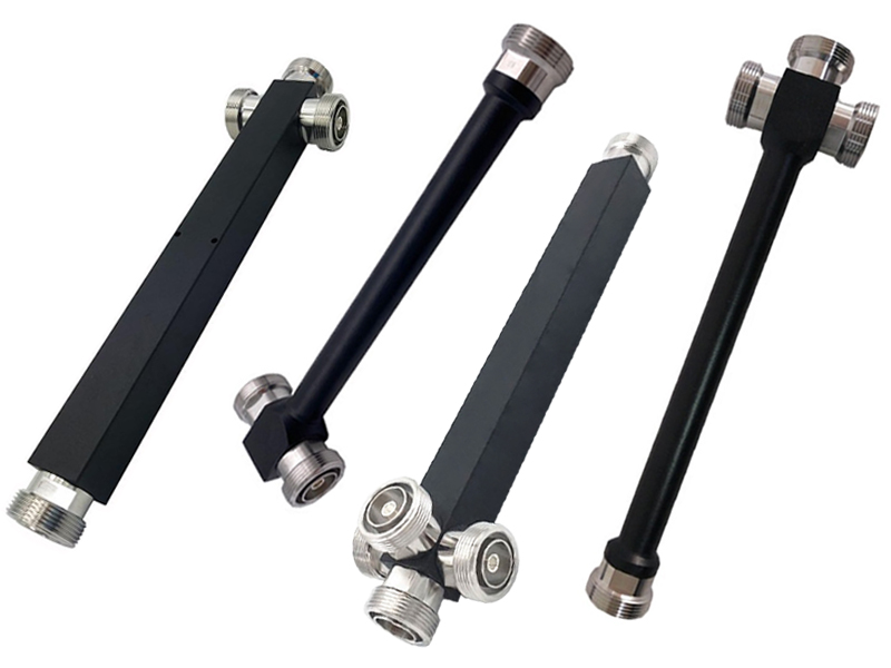
A 7/16 DIN power splitter is a passive device that divides a single RF input into two or more outputs while maintaining matched impedance and high isolation between ports. These splitters are the backbone of signal distribution in macro cells, DAS head‑ends, broadcast transmitters, and test laboratories that handle significant power levels.
7/16 DIN power splitters are classified according to circuit topology, port configuration, power rating, frequency coverage, and PIM performance grade.
Wilkinson Power Splitters
The Wilkinson topology is the industry standard for 7/16 DIN splitters used in infrastructure and broadcast. Named after its inventor, the Wilkinson splitter uses quarter-wave transmission lines and internal isolation resistors to achieve excellent performance.
Low insertion loss: Excess loss typically 0.1–0.3 dB above theoretical split loss.
High isolation: 20–30 dB between output ports, critical for preventing interference.
Excellent VSWR: Typically 1.15:1 to 1.25:1 across the operating band.
Low-PIM capability: Can reliably achieve –160 dBc to –165 dBc with proper materials and assembly.
Band‑optimized: Best performance over narrow to multi‑octave bands (e.g., 698–960 MHz, 1710–2700 MHz, or 698–2700 MHz broadband designs).
Wilkinson splitters are the default choice for all high‑performance, high‑power applications, including cellular base stations, broadcast transmitters, and public safety networks.
Resistive Power Splitters
Resistive splitters use a network of precision thin‑film resistors to divide power. They are less common in 7/16 DIN because the interface is typically chosen for high‑efficiency applications, and resistive designs introduce significant loss (6–8 dB for a 2‑way split, compared to the 3 dB theoretical split loss). However, they appear in certain test and wideband monitoring applications where ultra‑broadband response (DC to several GHz) is valued over insertion loss.
Hybrid Couplers (90‑degree / 180‑degree)
For applications requiring quadrature or differential outputs, 7/16 DIN hybrid couplers are available. These devices split power equally but introduce a fixed phase shift (90° or 180°) between outputs, essential for feeding phased‑array antennas, I/Q modulators, and balanced amplifiers.
7/16 DIN splitters are available in a wide range of port counts, from simple 2‑way to complex 16‑way and beyond.
| Port Count | Theoretical Split Loss | Typical Field of Use |
| 2-way | 3.0 dB | Base station sector feeds, redundant system switching |
| 3-way | 4.8 dB | Three‑sector macro cells (common in many LTE/5G deployments) |
| 4-way | 6.0 dB | Multi‑antenna sites, DAS head‑ends |
| 6-way | 7.8 dB | Medium‑scale distribution (e.g., building entrance) |
| 8-way | 9.0 dB | Large DAS nodes, campus distribution hubs |
| 12-way / 16-way | 10.8 / 12.0 dB | High‑density distribution, broadcast transmitter combining |
Higher port counts are generally realized by cascading multiple 2‑way Wilkinson stages inside a single rugged housing. The large size of the 7/16 DIN connector means that multi‑way splitters are physically substantial, but this also provides excellent heat dissipation for high‑power operation.
Power handling is a primary differentiator for 7/16 DIN splitters. The robust interface allows for average power ratings that far exceed those of N‑type or SMA.
Low‑to‑medium power (30–150 W): Suitable for small cells, low‑power remote radio heads, and indoor DAS.
High power (150–300 W): Standard for macro‑cell base stations and general broadcast transmitters.
Very high power (300–600 W+): Designed for high‑power broadcast (FM/TV), high‑power radar, and industrial RF systems (e.g., plasma generators). These units often incorporate finned aluminum housings or forced‑air cooling.
It is important to note that the splitter’s power rating applies to continuous wave (CW) operation at a specified ambient temperature (usually +40°C). Derating curves apply at higher temperatures. For pulsed applications, peak power can reach several kilowatts as long as the average power remains within the continuous rating.
7/16 DIN splitters are optimized for the frequency bands used in cellular, broadcast, and other high‑power services.
Low‑band only (698–960 MHz): Covers LTE bands 5, 8, 12, 13, 14, 17, 20, 28, etc.
Mid‑band only (1710–2700 MHz): Covers PCS, AWS, DCS, LTE bands 1, 2, 3, 4, 7, 25, 66, 40 (2300 MHz).
High‑band (3400–4200 MHz): For C‑band 5G deployments.
Dual‑band / Broadband (698–2700 MHz or 698–3800 MHz): Single splitter covering most sub‑4 GHz cellular bands, simplifying inventory and reducing insertion points.
Extended‑range (DC–6 GHz or DC–7.5 GHz): Precision resistive designs or high‑bandwidth Wilkinson designs for test and military applications.
While the 7/16 DIN connector can theoretically operate beyond 7.5 GHz, most infrastructure splitters are specified only up to 6 GHz because cellular bands currently extend only to about 4.2 GHz for sub‑6 GHz 5G.
Passive Intermodulation (PIM) is arguably the most critical specification for splitters used in multi‑carrier, multi‑operator cellular environments. 7/16 DIN splitters are classified into three typical PIM grades:
Standard PIM: –150 dBc or –153 dBc. Adequate for single‑operator sites or less congested environments.
Low PIM: –155 dBc to –158 dBc. Suitable for typical multi‑carrier base stations.
Ultra‑Low PIM: –160 dBc to –165 dBc (and occasionally –170 dBc). Required for high‑density urban sites, shared infrastructure, and low‑band (700 MHz) systems where PIM products fall directly into receive bands.
The 7/16 DIN interface’s large, smooth contact surfaces, high mating pressure, and absence of ferromagnetic materials (in quality designs) make it inherently capable of excellent PIM performance.
When selecting a 7/16 DIN power splitter, engineers must evaluate a suite of electrical and mechanical parameters. The table below summarizes typical specifications for a high‑grade infrastructure Wilkinson splitter covering 698–2700 MHz.
| Parameter | Typical Specification (Wilkinson, 2‑way) | Notes |
| Frequency range | 698–2700 MHz (or 698–3800 MHz, or band‑specific) | Covers all standard cellular bands |
| Insertion loss (2‑way) | ≤ 3.3 dB (typically 3.2 dB) | Includes 3.0 dB split loss |
| Excess loss | ≤ 0.3 dB (typically 0.2 dB) | Very low due to large, low‑loss transmission lines |
| Amplitude balance | ±0.3 dB (typical ±0.2 dB) | Consistency between outputs |
| Phase balance | ±3° (typical ±2°) | Important for MIMO and phased arrays |
| Isolation (port to port) | ≥ 25 dB (often 30 dB typical) | Prevents crosstalk and receiver desensitization |
| Input VSWR | ≤ 1.20:1 (typical 1.15:1) | Excellent impedance match |
| Output VSWR | ≤ 1.20:1 | Matched for all output ports |
| PIM (2 × 43 dBm carriers) | ≤ –160 dBc (ultra‑low grade) | Some premium units achieve –165 dBc |
| Average power handling | 200–300 W (CW) | Derate at elevated temperatures |
| Peak power (pulsed) | 2–5 kW (typ. 10 µs pulse) | Limited by connector and internal components |
| Operating temperature | –40°C to +85°C (outdoor grade) | Some industrial grades extend to –55°C to +125°C |
| Impedance | 50 Ω | Standard |
| Connector gender | Female (jack) on all ports, or male on input | Typically N female (7/16 DIN female) for outdoor use |
| Ingress protection | IP67 (when mated) | Common for tower‑top and outdoor cabinet installations |
Insertion Loss and Excess Loss
The theoretical split loss for a 2‑way splitter is 3.0 dB. In practice, high‑quality Wilkinson splitters add only 0.1–0.3 dB of excess loss due to conductor resistance, dielectric losses, and imperfect matching. For a 4‑way splitter, the theoretical loss is 6.0 dB, and high‑grade units achieve total insertion loss of 6.2–6.4 dB. Low insertion loss is critical in transmit paths where every tenth of a decibel represents wasted power and reduced coverage.
VSWR (Voltage Standing Wave Ratio)
7/16 DIN splitters achieve outstanding VSWR because the large interface and robust construction minimize impedance discontinuities. A VSWR of 1.20:1 corresponds to a return loss of about 20.8 dB (less than 1% reflected power). Precision versions achieve 1.15:1 (23.1 dB return loss) or better.
Isolation
Isolation between output ports prevents transmitter energy from leaking into other outputs that may be connected to sensitive receivers. In a typical base station with frequency division duplex (FDD), the transmit signal on one output must not couple into the receive path on another output. Isolation of 25–30 dB provides adequate protection for most systems.
PIM (Passive Intermodulation)
For 7/16 DIN splitters used in cellular base stations, PIM is often the most closely watched specification. The test uses two +43 dBm (20 W) carriers spaced apart (e.g., at 1930 MHz and 1990 MHz) and measures the third‑order product at 2f1–f2 (e.g., 1870 MHz). A specification of –160 dBc means the PIM product is 160 dB below one carrier, i.e., –117 dBm absolute—an extremely low level. Achieving this requires careful material selection (no ferromagnetic metals), high‑quality plating (silver or low‑PIM nickel), and clean, precise assembly.
Power Handling and Thermal Management
The large size of the 7/16 DIN connector and the splitter’s housing provide significant thermal mass and surface area for heat dissipation. Many high‑power splitters are housed in finned aluminum enclosures to further enhance cooling. Users must follow derating guidelines when operating at elevated ambient temperatures (e.g., in an unventilated outdoor cabinet in summer).
Environmental Ratings
Outdoor‑grade 7/16 DIN splitters typically carry IP67 or IP68 ratings when mated, meaning they are protected against dust ingress and temporary immersion in water. The operating temperature range of –40°C to +85°C covers virtually all terrestrial outdoor environments. Some industrial models extend to –55°C to +125°C for extreme conditions.
The following table compares 7/16 DIN to other common connector interfaces for power splitters.
| Feature | 7/16 DIN | 4.3‑10 | N‑Type | SMA |
| Power handling (CW) | Very high (200–600+ W) | High (100–300 W) | Medium (50–200 W) | Low (1–50 W) |
| PIM performance | Excellent (≤ –165 dBc) | Excellent (≤ –165 dBc) | Good (≤ –150 dBc) | Poor (often not specified) |
| Size / weight | Large / heavy | Medium (50% smaller than 7/16) | Medium | Very small / light |
| Port density | Low | High | Medium | Very high |
| Frequency range | DC–6 GHz (7.5 GHz premium) | DC–6 GHz | DC–11/18 GHz | DC–18/26.5 GHz |
| Mating torque | 3.0–3.5 Nm (high) | 1.0–1.5 Nm | 1.0–1.5 Nm | 0.7–0.9 Nm |
| Environmental sealing | Excellent (IP67/68) | Good (IP67) | Good (IP67 possible) | Poor (indoor only) |
| Typical application | Macro cells, broadcast | Small cells, DAS, macro cells | General RF, test | Lab, low‑power |
For applications requiring the highest power handling, proven low‑PIM, and extreme environmental durability, the 7/16 DIN splitter remains the preferred choice, despite its larger size and higher cost.
Macro‑Cell Base Stations
The largest market for 7/16 DIN splitters is cellular infrastructure, particularly macro cells that serve wide geographic areas. These splitters are used to feed sector antennas, distribute test signals, and combine multiple carriers. Despite the industry’s gradual move toward 4.3‑10 for new builds, the enormous installed base of 7/16 DIN equipment ensures continued demand.
Broadcast Transmitters
FM radio, TV, and digital broadcast (DVB‑T/T2) transmitters often use high‑power 7/16 DIN splitters to feed multiple antenna bays or to combine outputs from several transmitters into a single antenna system. Power ratings of 500 W or more are common.
Radar and Defense
Ground‑based radar, naval radar, and some airborne systems use 7/16 DIN connectors for their high‑power handling and ruggedness. Splitters in these applications are often custom‑designed for specific frequency bands (e.g., L‑band, S‑band) and must meet stringent MIL‑spec environmental requirements.
Industrial RF Heating
Industrial applications such as plasma generation, materials processing, and medical diathermy use 7/16 DIN splitters to distribute high‑power RF energy (often 100–500 W at 13.56 MHz, 27.12 MHz, or 915 MHz).
Test and Measurement
High‑power test labs and calibration facilities use 7/16 DIN splitters to divide signals for testing amplifiers, filters, and antennas. For these applications, excellent VSWR and amplitude/phase stability are critical.
When specifying a 7/16 DIN power splitter, engineers should consider the following factors.
| Factor | Recommendations |
| Power requirements | Calculate average and peak power; select a splitter with a rating at least 20–30% higher than the maximum operating level. Derate for high ambient temperatures. |
| Frequency coverage | Ensure the splitter’s specified frequency range includes all operating bands, including any future expansion bands. |
| PIM performance | For multi‑carrier cellular sites, specify –160 dBc or better. For single‑carrier or non‑critical sites, –153 dBc may suffice. |
| Isolation needs | If the splitter feeds a receiver on one port and a transmitter on another, choose a design with ≥ 25 dB isolation. |
| Port count | Match the number of outputs to the system architecture; avoid using splitters with unused ports (terminate them). |
| Environmental requirements | For outdoor use, verify IP rating and operating temperature range. For tower‑top deployment, also check UV resistance and salt‑spray corrosion protection. |
| Connector gender | Typically all ports are female (jack) to mate with male (plug) cables. Some designs offer a male input for direct connection to a transmitter. |
| Mechanical footprints | Ensure the splitter’s physical dimensions and mounting provisions (e.g., bracket, grounding lug) are compatible with the equipment rack or cabinet. |
To achieve the specified performance and longevity from a 7/16 DIN power splitter:
Use a torque wrench: Apply the correct torque (typically 3.0–3.5 Nm or 25–30 in‑lbs) to all connectors. Over‑torquing can damage the interface; under‑torquing degrades PIM and may cause intermittent contact.
Terminate unused ports: Always install a 50 Ω terminator (preferably a low‑PIM load) on any unused output port to prevent reflections and unintentional radiation.
Keep connectors clean: Clean mating surfaces with isopropyl alcohol and PIM‑safe swabs before each connection. Contamination is a leading cause of high PIM.
Use non‑ferromagnetic hardware: When mounting splitters, use brass, stainless steel (non‑magnetic), or aluminum brackets and fasteners to avoid introducing PIM sources.
Allow for heat dissipation: Do not block the splitter’s ventilation or heatsink fins. Mount with adequate airflow for high‑power models.
Ground properly: Ensure the splitter’s body is bonded to system ground to prevent static buildup and improve safety.
The 7/16 DIN power splitter is not being replaced overnight. While newer interfaces like 4.3‑10 gain traction in new builds—especially for small cells and dense urban macro sites—the 7/16 DIN remains the standard for high‑power, legacy, and many existing networks. Manufacturers continue to refine these splitters with:
Extended frequency ranges: Some new models support up to 6 GHz or 7.5 GHz to accommodate 5G mid‑band and C‑band.
Improved PIM: Advanced plating and assembly techniques push PIM performance beyond –165 dBc.
Hybrid designs: Integration of splitters with filters (diplexers, triplexers) or bias‑T circuits reduces insertion loss and footprint.
Environmental hardening: IP68 ratings and enhanced corrosion protection for direct‑burial or coastal installations.
According to industry analysts, the 7/16 DIN splitter market will remain stable for the next decade, driven by the massive installed base and the need for backward compatibility. New deployments may increasingly favor 4.3‑10, but for applications where proven reliability and maximum power handling are paramount, 7/16 DIN splitters will continue to be the component of choice.