

-
We’re On Call 24/7 : +8613538296050
-
E-mail : anna@rohoconnector.com
We’re On Call 24/7 : +8613538296050
E-mail : anna@rohoconnector.com
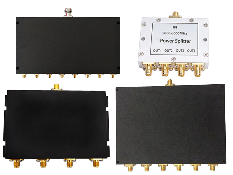
As wireless networks evolve toward higher frequencies and greater complexity, the demand for compact, high-performance signal distribution components has never been more critical. Among these, SMA power splitters—also known as power dividers—have emerged as indispensable tools for engineers working in telecommunications, aerospace, defense, and test instrumentation. Leveraging the robust SubMiniature version SMA connector interface, these passive devices split a single RF input signal into multiple outputs with minimal loss, excellent isolation, and precise amplitude and phase matching.
This news report examines the classification and key performance characteristics of SMA power splitters, providing industry professionals with essential insights for component selection in demanding RF environments.
SMA power splitters are categorized primarily by their internal circuit topology, port configuration, power handling capability, and impedance. Each classification directly influences the device's electrical performance and suitability for specific applications.
Wilkinson Power Splitters
The Wilkinson design is the industry standard for applications requiring low insertion loss and high isolation between output ports. These splitters utilize quarter-wave transmission line sections and internal isolation resistors to achieve excellent performance over multi-octave bandwidths. A Wilkinson splitter ensures that each output port remains impedance-matched and that signals from different outputs do not interfere with one another.
Key characteristics of Wilkinson splitters include:
Low insertion loss (excess loss typically 0.1–0.5 dB above the theoretical split loss)
High isolation (typically 20–30 dB between output ports)
Good VSWR (typically 1.2:1 to 1.5:1)
Matched phase and amplitude between outputs
These splitters are available in 2-way, 3-way, 4-way, and higher port counts. They are preferred for most telecommunications, radar, and test applications where signal integrity is paramount.
Resistive Power Splitters
Resistive designs employ a network of precision thin-film resistors to divide the signal. While they introduce higher insertion loss (typically 6–8 dB for a 2-way split, compared to the theoretical 3 dB split loss), they offer ultra-wideband performance from DC to frequencies exceeding 18 GHz. The resistive approach also provides excellent return loss at all ports and stable performance across temperature.
Key characteristics of resistive splitters include:
Very wide bandwidth (DC to 18 GHz or higher)
Higher insertion loss (typically 6–8 dB for 2-way)
Moderate isolation (typically 6–10 dB between outputs)
Excellent amplitude flatness across frequency
Resistive splitters are ideal for broadband test setups, instrumentation, and applications where extreme frequency coverage outweighs the need for high isolation.
SMA power splitters are manufactured in a wide range of port configurations to suit diverse system requirements:
2-way splitters: The most common configuration, available in both Wilkinson and resistive designs
3-way splitters: Typically Wilkinson designs with unequal power division or equal division using more complex networks
4-way splitters: Often implemented as a cascade of 2-way stages or as a single-stage Wilkinson network
6-way, 8-way, 12-way, and 16-way splitters: Usually constructed using multiple 2-way stages in a binary tree configuration
Higher port counts generally result in increased insertion loss due to the cumulative split loss and additional transmission line lengths.
SMA splitters span a wide range of power ratings:
Low-power (0.1–2 watts): Suitable for signal-level distribution, receiver front-ends, and laboratory test setups
Medium-power (2–30 watts): Common in wireless infrastructure, small-cell base stations, and general-purpose RF systems
High-power (30–100+ watts): Used in broadcast transmitters, high-power amplifier test, and radar systems
Higher power handling typically requires larger housing with enhanced thermal dissipation, though the compact SMA form factor inherently limits maximum power compared to larger connectors like N-type.
The vast majority of SMA power splitters are designed for 50-ohm systems, the standard for RF communications and test equipment. However, 75-ohm versions are available for video broadcast, CATV, and certain data communication applications.
When selecting an SMA power splitter, engineers must evaluate several critical performance parameters to ensure optimal system operation.
Insertion loss measures the signal power lost as it passes from input to output. For a theoretical 2-way splitter, the unavoidable 3.0 dB loss (half the power to each output) is considered the "split loss." Any additional loss above this value is "excess loss" caused by non-ideal components and transmission line losses.
Theoretical split loss: 3.0 dB (2-way), 4.8 dB (3-way), 6.0 dB (4-way), 9.0 dB (8-way), 12.0 dB (16-way)
Typical excess loss for Wilkinson designs: 0.1–0.5 dB
Typical excess loss for resistive designs: 3–5 dB above split loss
High-quality Wilkinson splitters achieve total insertion loss very close to the theoretical split loss, with excess loss as low as 0.1 dB in narrowband designs.
Isolation specifies how well signals on one output port are prevented from coupling into another output port. It is measured in decibels (dB), with higher values indicating better isolation. Poor isolation leads to crosstalk, signal corruption, and potential instability in systems with receivers connected to multiple outputs.
Wilkinson splitters: Typically 20–30 dB isolation across the operating band
Resistive splitters: Typically 6–10 dB isolation
Premium designs: Can achieve 35 dB or higher isolation in narrow bands
Isolation is particularly critical in applications where one output connects to a sensitive receiver while another output carries a high-power transmitter signal.
VSWR indicates the quality of the impedance match at the input and output ports. A perfect match would have a VSWR of 1.00:1, meaning all incident power is absorbed with zero reflection. In practice, quality SMA splitters achieve:
Input VSWR: Typically 1.2:1 to 1.5:1
Output VSWR: Typically 1.2:1 to 1.5:1
Precision designs: Can achieve 1.10:1 or better
Low VSWR ensures efficient power transfer and minimizes reflections that can distort signals and damage sensitive sources.
For splitters with multiple outputs, amplitude balance specifies the maximum deviation in signal level between any two outputs. This is critical for applications such as phased array antennas, I/Q modulators, and balanced receivers.
Standard grade: ±0.3 dB to ±0.5 dB
Precision grade: ±0.1 dB to ±0.2 dB
Resistive designs: Often ±0.2 dB or better across wide bandwidths
Phase balance specifies the maximum deviation in phase angle between output signals. It is essential for coherent systems such as beamforming networks, interferometers, and I/Q demodulators.
Standard grade: ±3° to ±5°
Precision grade: ±1° to ±2°
Narrowband designs: Can achieve ±0.5° or better
SMA connectors are typically specified for operation up to 18 GHz, but high-performance splitters extend this range considerably:
Standard SMA splitters: DC to 18 GHz
Extended range SMA splitters: DC to 26.5 GHz or 27 GHz
Precision designs: Up to 40 GHz with enhanced connector interfaces
Below 500 MHz, SMA splitters remain effective, though larger connectors may offer lower loss. The usable frequency range must be matched to the application's operating band.
Power rating is typically specified as the maximum continuous wave (CW) input power that the splitter can safely handle without degradation or failure. Key considerations include:
Average power rating: Ranges from 0.1 watts to 100 watts depending on design and housing
Peak power rating: For pulsed applications, peak power can be significantly higher (kilowatts for short pulses)
Derating: Power handling decreases at elevated ambient temperatures
Operating temperature: Most SMA splitters are rated from -55°C to +85°C or -40°C to +85°C
Return loss is the logarithmic expression of VSWR and is often used interchangeably. High return loss indicates good impedance matching:
20 dB return loss corresponds to VSWR 1.22:1
25 dB return loss corresponds to VSWR 1.12:1
30 dB return loss corresponds to VSWR 1.07:1
Precision splitters specify return loss of 20 dB or better across their operating band.
SMA power splitters serve critical functions across multiple industries:
Telecommunications: Distributing signals from base stations to multiple antennas, feeding sectorized cells, and splitting test signals for drive testing and network monitoring.
Test and Measurement: Dividing reference signals to multiple instruments, providing multiple channels for simultaneous measurements, and creating calibration setups for vector network analyzers.
Aerospace and Defense: Feeding phased array radar elements, distributing signals in electronic warfare systems, and splitting telemetry signals in satellite payloads.
Commercial Wireless: Supporting in-building distributed antenna systems (DAS), small cell deployments, and public safety communication networks.
Research and Development: Enabling multi-channel measurements in laboratories, supporting prototype evaluation, and characterizing new RF components.
When selecting an SMA power splitter, consider the following factors:
| Factor | Guidelines |
| Frequency range | Ensure the splitter covers your operating band with margin for harmonics |
| Insertion loss | Accept theoretical split loss plus minimal excess loss; resistive designs add 3–5 dB |
| Isolation | Wilkinson (20-30 dB) for most systems; resistive (6-10 dB) acceptable for broadband test |
| VSWR | ≤1.3:1 for precision work; ≤1.5:1 for general applications |
| Amplitude/phase balance | Critical for phased arrays and I/Q systems; specify ±0.2 dB and ±2° for precision |
| Power handling | Select rating with 20-30% safety margin above maximum operating power |
| Port configuration | Match the number of outputs to system requirements; avoid unused ports |
| Impedance | 50 ohm for RF/telecom; 75 ohm for video/broadcast |
| Environmental conditions | Verify temperature range and any sealing requirements for outdoor use |
The market for SMA power splitters continues to evolve in response to several key trends:
Higher frequencies: As 5G-Advanced and 6G push into millimeter-wave bands (24–100 GHz), SMA splitters are being redesigned with improved materials and tighter tolerances to maintain performance at extended frequencies.
Miniaturization: The demand for smaller, lighter components in portable and airborne systems drives the development of ultra-compact SMA splitters with surface-mount or miniature housing.
Improved thermal management: Higher power densities require innovative heat dissipation techniques, including thermally conductive housings and optimized internal layouts.
Enhanced phase and amplitude stability: Coherent systems and massive MIMO arrays demand splitters with exceptional phase and amplitude matching over temperature and time.
Integration: Some manufacturers are integrating splitters with other functions (filters, amplifiers, attenuators) into single modules to reduce system footprint and improve reliability.