

-
We’re On Call 24/7 : +8613538296050
-
E-mail : anna@rohoconnector.com
We’re On Call 24/7 : +8613538296050
E-mail : anna@rohoconnector.com
As the wireless communications industry accelerates toward 5G-Advanced, 6G, and beyond, the demand for components capable of operating at millimeter-wave frequencies has never been greater. At the forefront of this technological frontier stands the 2.4mm terminator, a precision coaxial component engineered to deliver exceptional performance from DC to 50 GHz. With its robust mechanical design, superior electrical characteristics, and compatibility with other high-frequency interfaces, the 2.4mm terminator has become indispensable in advanced test and measurement, aerospace and defense, satellite communications, and next-generation wireless research.
Developed in the late 1980s to address the limitations of smaller connectors like the 2.92mm, the 2.4mm interface was designed specifically for high-frequency applications requiring repeatable, low-reflection terminations. Its air-dielectric construction and precision machining allow it to maintain excellent impedance matching well into the millimeter-wave spectrum, making it the connector of choice for engineers pushing the boundaries of frequency and performance.
The 2.4mm connector derives its name from the outer conductor diameter of 2.4 millimeters. Unlike its 2.92mm predecessor—which operates reliably to 40 GHz—the 2.4mm interface was purpose-built for frequencies up to 50 GHz, with some precision variants capable of functioning even higher. The connector features an air-dielectric interface, minimizing loss and ensuring stable characteristic impedance across its operating range.
One of the most significant advantages of the 2.4mm interface is its intermateability with other precision connector families:
2.4mm connectors are fully compatible with 1.85mm connectors (operating to 67 GHz) and 1.0mm connectors (operating to 110 GHz) when using appropriate adapters, though direct mating is not recommended without proper consideration of pin depth tolerances.
2.4mm connectors are not directly compatible with 2.92mm, 3.5mm, or SMA connectors, as the interface dimensions and pin depths differ significantly. Adapters are required for mixed-interface connections.
This compatibility hierarchy makes 2.4mm terminators an essential bridge component in multi-interface test setups, allowing engineers to maintain signal integrity across frequency bands.
2.4mm terminators can be classified according to power handling capability, mechanical configuration, precision grade, and application-specific features.
Power handling in 2.4mm components is inherently limited by the small physical dimensions of the interface. Nevertheless, manufacturers offer a range of power ratings to suit different applications:
| Power Class | Typical Average Power | Applications |
| Low-Power | 0.25 W – 0.5 W | Signal-level terminations, receiver ports, sensitive measurement setups |
| Standard-Power | 0.5 W – 2 W | General-purpose RF testing, benchtop instrumentation, component characterization |
| High-Power | 2 W – 10 W | Specialized high-power amplifier testing (with derating at higher frequencies) |
Most standard 2.4mm terminators are rated for 0.5 W to 2 W average power at 50 GHz, with derating curves applied at elevated temperatures. Peak power handling for pulsed applications can be significantly higher, often specified in kilowatts for narrow pulse widths.
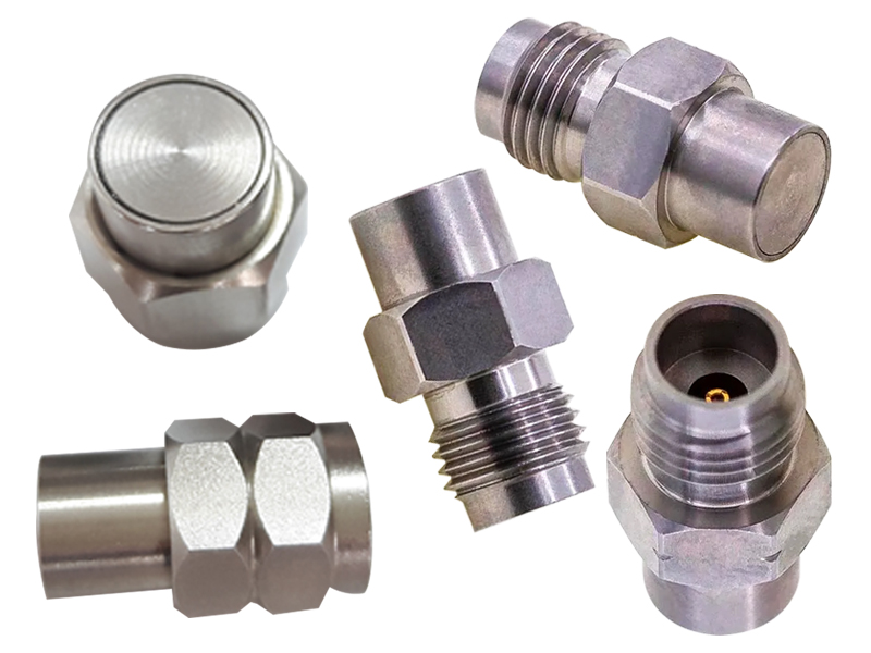
Male (Plug) Terminators: Feature a center pin and a threaded coupling nut. Used to terminate female connectors on cables, test ports, or devices.
Female (Jack) Terminators: Feature a center socket and a threaded body. Used to terminate male connectors.
Precision Calibration Terminators: Often supplied as part of calibration kits, these devices are individually measured and supplied with traceable VSWR or return loss data. They may feature proprietary torque specifications and enhanced stability.
Right-Angle Terminators: Available for applications with severe space constraints, though they introduce additional electrical complexity and are less common than straight configurations.
Standard Grade: Designed for general laboratory, production test, and system integration use. These terminators offer excellent VSWR performance (typically ≤ 1.25:1 to 50 GHz) and are cost-effective for routine applications.
Precision / Metrology Grade: Manufactured to tighter tolerances and individually tested, these terminators achieve VSWR ratings as low as 1.10:1 or better across their frequency range. They are essential components in calibration kits for vector network analyzers (VNAs) and other precision measurement equipment.
Aerospace / Military Grade: Built to meet stringent MIL specifications, these terminators feature enhanced durability, extended temperature ranges, and rigorous screening processes for use in defense and space applications.
2.4mm terminators are exclusively designed for 50 Ω systems, adhering to the standard for high-frequency RF, microwave, and millimeter-wave applications.
The performance of a 2.4mm terminator is defined by several critical parameters that must be carefully evaluated for each application.
The defining characteristic of the 2.4mm interface is its ability to operate to 50 GHz with exceptional performance. High-quality terminators maintain specified VSWR and return loss across the entire DC to 50 GHz range. Some precision models are rated to 55 GHz or even 60 GHz, though the connector's design limit is typically 50 GHz for guaranteed specifications. This wide bandwidth makes 2.4mm terminators suitable for applications spanning traditional microwave frequencies through the millimeter-wave bands used in 5G (28 GHz, 39 GHz), automotive radar (77 GHz), and satellite communications (Ka-band).
VSWR is the paramount specification for any terminator, quantifying the quality of the impedance match. For 2.4mm terminators:
| Grade | VSWR Specification | Return Loss (typical) |
| Standard Grade | ≤ 1.25:1 to 50 GHz | 19.1 dB |
| Precision Grade | ≤ 1.15:1 to 50 GHz | 23.1 dB |
| Metrology Grade | ≤ 1.10:1 to 50 GHz | 26.4 dB |
| Ultra-Precision | ≤ 1.08:1 to 50 GHz | 28.5 dB |
These low VSWR values ensure minimal signal reflection, which is essential for accurate network analyzer calibrations, precise power measurements, and the protection of sensitive millimeter-wave sources and amplifiers.
Return loss, expressed in decibels (dB), is the logarithmic representation of VSWR. High return loss values indicate better performance. For precision 2.4mm terminators, return loss of > 26 dB across the full bandwidth is common, meaning that less than 0.25% of incident power is reflected back toward the source.
Power ratings for 2.4mm terminators are typically specified as average continuous wave (CW) power at room temperature. A standard 2.4mm terminator handles 0.5 W to 2 W . Power handling decreases with frequency due to increased losses in the transmission line structure and with temperature due to reduced thermal dissipation capacity. Derating curves are provided by manufacturers to guide safe operation at elevated temperatures.
For pulsed applications, peak power ratings can be significantly higher. Many 2.4mm terminators are rated for peak power handling of 100 W to 500 W for short pulse widths (typically 1-10 μs) and low duty cycles.
The materials used in a 2.4mm terminator directly impact its electrical performance, durability, and stability.
Body: Typically stainless steel, passivated for corrosion resistance. Stainless steel provides excellent mechanical strength and thermal stability, essential for maintaining precise dimensions that affect impedance.
Center Contact: Beryllium copper (BeCu) or beryllium nickel, with gold plating over a nickel underplate. These materials offer a combination of high conductivity, mechanical strength, and spring properties that ensure reliable electrical contact over hundreds of mating cycles.
Dielectric: Air is the primary dielectric in the interface region, minimizing loss and dispersion. Support beads are typically PTFE (polytetrafluoroethylene) or a proprietary low-loss material.
Coupling Nut: Stainless steel with a consistent torque specification (typically 8-10 in-lbs) to ensure repeatable connections and prevent damage.
2.4mm terminators are designed for demanding environments, with specifications that reflect their use in advanced test labs, field deployments, and aerospace applications.
| Parameter | Typical Specification |
| Operating Temperature | -55 °C to +125 °C (precision grades) |
| Storage Temperature | -55 °C to +125 °C |
| Mating Cycles | ≥ 500 (standard), ≥ 1000 (ruggedized) |
| Torque Specification | 8-10 in-lbs (0.9-1.1 Nm) |
| Center Contact Retention | ≥ 1.5 lbs axial force |
For applications requiring precise phase relationships—such as phased array antenna testing, coherent radar systems, and quantum computing experiments—phase stability is a critical consideration. Precision 2.4mm terminators often specify phase stability versus temperature, typically expressed in degrees per °C per GHz. Premium models achieve phase stability better than 0.05°/°C/GHz.
When used as calibration standards, 2.4mm terminators must be supplied with individual test data traceable to national metrology institutes such as NIST (USA), NPL (UK), or PTB (Germany). These data typically include:
VSWR or return loss measurements at defined frequency points
DC resistance measurement
Phase information for calibration kit definitions
Uncertainty analysis for metrology-grade components
The 2.4mm terminator occupies a critical position in the millimeter-wave ecosystem, serving applications across multiple high-growth sectors.
As wireless communications extend into the millimeter-wave spectrum, 2.4mm components are essential for characterizing 5G transceivers operating at 28 GHz, 39 GHz, and beyond. Research into 6G technologies, targeting frequencies from 100 GHz to 300 GHz, relies heavily on 2.4mm and smaller form factors for component-level testing.
Radar systems operating in K-band (18-27 GHz) and Ka-band (27-40 GHz) depend on 2.4mm terminators for system integration, test, and calibration. Electronic warfare systems, satellite communications payloads, and missile guidance systems also utilize these components extensively.
The rise of high-speed digital standards (PCIe, USB4, Ethernet) with data rates exceeding 100 Gb/s requires characterization of channel behavior up to millimeter-wave frequencies. 2.4mm terminators are used in time-domain reflectometry (TDR) and vector network analyzer measurements of high-speed interconnects.
Automotive radar systems operating at 77 GHz and 79 GHz for autonomous driving applications require precision components for testing and calibration. While 1.0mm and 1.35mm connectors are more common at these frequencies, 2.4mm components serve as critical interfaces for system-level test and development.
Quantum computing, radio astronomy, and particle accelerator facilities rely on high-frequency components for signal distribution and termination. 2.4mm terminators provide the precision and repeatability required for these demanding scientific applications.
Understanding the positioning of 2.4mm terminators relative to other interfaces helps engineers select the optimal component for their needs.
| Interface | Frequency Limit | Compatibility | Primary Applications |
| SMA | 18 GHz | Standard lab use | General RF, test equipment |
| 3.5mm | 34 GHz | Compatible with SMA | Precision measurement, aerospace |
| 2.92mm (K) | 40 GHz | Compatible with 3.5mm | 5G, satellite, test |
| 2.4mm | 50 GHz | Compatible with 1.85mm | Millimeter-wave, defense, research |
| 1.85mm | 67 GHz | Compatible with 2.4mm | Advanced millimeter-wave |
| 1.0mm | 110 GHz | None (direct) | Terahertz research, 6G |
When specifying a 2.4mm terminator for your application, consider these key factors:
| Factor | Considerations |
| Frequency Range | Ensure the terminator's specified frequency range covers your maximum operating frequency, including harmonics if testing nonlinear devices. |
| VSWR / Return Loss | For calibration and precision measurements, select metrology grade (≤ 1.10:1). For general test and system integration, standard grade (≤ 1.25:1) is usually sufficient. |
| Power Handling | Calculate average and peak power levels; select a terminator with adequate headroom. Apply derating for elevated temperatures. |
| Connector Gender | Match the gender to the port: male terminator for female port, female terminator for male port. |
| Torque Requirements | Follow manufacturer torque specifications to prevent damage to precision connectors. |
| Calibration Data | For metrology applications, verify that terminators are supplied with traceable test data. |
| Environmental Conditions | Consider temperature extremes, humidity, and mechanical stress; select appropriate grade for your operating environment. |
The market for 2.4mm terminators and related millimeter-wave components is projected to grow at a compound annual growth rate exceeding 12% through 2030, driven by 5G expansion, the emergence of 6G research programs, and continued investment in aerospace and defense systems. Major manufacturers including Amphenol, Cinch Connectivity Solutions, Fairview Microwave, Mini-Circuits, Pasternack, Radiall, Rosenberger, and Spectrum Control continue to expand their 2.4mm product portfolios, introducing higher-performance terminators with improved VSWR, extended frequency ranges, and enhanced environmental specifications.