

-
We’re On Call 24/7 : +8613538296050
-
E-mail : anna@rohoconnector.com
We’re On Call 24/7 : +8613538296050
E-mail : anna@rohoconnector.com
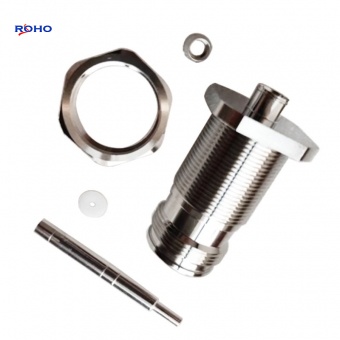
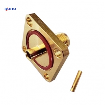
RF coaxial connectors are abbreviated as RF connectors. You know it. It is generally considered as an element attached to a cable or to an installation instrument as an electrical connecting or separating element of the transmission line. It belongs to mechatronic products. In simple terms, it serves as a bridge.
First,the radio frequency connector naming method
The model of the universal RF connector consists of two parts: the main code and the structure form code. The middle is separated by a dash "-". Other conditions that need to be specified can be specified in the detailed specification and separated by a dash.
Second, RF connector code description.
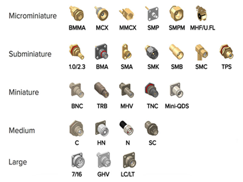
1. 17 kinds of appearance code introduction
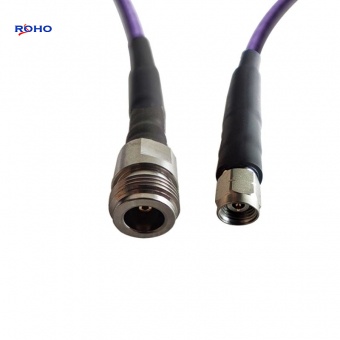
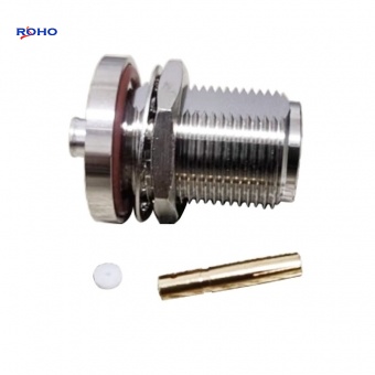
(1) Type N: Threaded RF coaxial connectors with an inner diameter of the outer conductor of 7mm (0.276 inch) and a characteristic impedance of 50 ohms (75 ohms). (IEC169-16)
(2) BNC Type: Bayonet locking RF coaxial connector with inner diameter of outer conductor of 6.5mm (0.256 inch) and characteristic impedance of 50Ω. (IEC169-8)
(3) Type TNC: Threaded RF coaxial connector with outer diameter of outer conductor of 6.5mm (0.256 inch) and characteristic impedance of 50Ω. (IEC169-17)
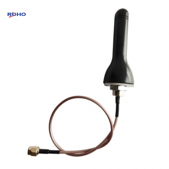
(4) Type SMA: Threaded RF coaxial connector with inner diameter of outer conductor of 4.13mm (0.163 inch) and characteristic impedance of 50Ω. (IEC169-15)
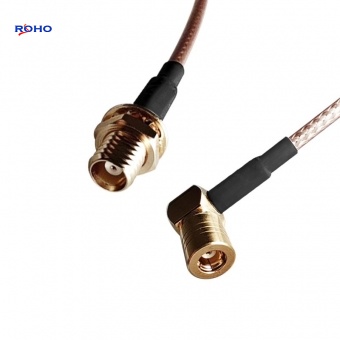
(5) SMB type: push-lock RF coaxial connector with inner diameter of outer conductor of 3mm (0.12 inch) and characteristic impedance of 50Ω. (IEC169-10)
(6) SMC type: RF coaxial connector with inner diameter of outer conductor of 3mm (0.12 inch) and characteristic impedance of 50Ω. (IEC169-9)
(7) SSMA Type: RF coaxial connector with inner diameter of outer conductor of 2.79mm (0.11 inch) and characteristic impedance of 50Ω. (IEC169-18)
(8) SSMB Type: Push-locked RF coaxial connector with inner diameter of outer conductor of 2.08mm (0.082 inch) and characteristic impedance of 50Ω. (IEC169-19)
(9) SSMC type: RF coaxial connector with inner diameter of outer conductor of 2.08mm (0.082 inch) and characteristic impedance of 50Ω. (IEC169-20)
(10) Type SC (SC-A and SC-B type): RF coaxial connector with inner diameter of outer conductor of 9.5mm (0.374 inch) and characteristic impedance of 50Ω (two types with different types of connecting threads). (IEC169-21)
(11) APC7 Type: Precision medium-sized RF coaxial connector with inner diameter of outer conductor of 7mm (0.276 inch) and characteristic impedance of 50Ω. (IEC457-2)
(12) APC3.5 Type: RF coaxial connector with inner diameter of outer conductor of 3.5mm (0.138 inch) and characteristic impedance of 50Ω. (IEC169-23)
(13) Type K: Threaded RF coaxial connector with inner diameter of outer conductor of 2.92mm (0.115 inch) and characteristic impedance of 50Ω.
(14) OS-50 Type: RF coaxial connector with inner diameter of outer conductor 2.4mm (0.095 inch) and characteristic impedance of 50Ω.
(15) Type F: Threaded RF coaxial connectors used in cable distribution systems with a characteristic impedance of 75Ω. (IEC169-24)
(16) Type E: Threaded RF coaxial connectors used in cable distribution systems with a characteristic impedance of 75Ω. (IEC169-27)
(17) L type: Metric thread type RF coaxial connector, thread size is indicated by Arabic numerals after "L".
2. The structure of the generic RF connector is coded by the following table:
standard
Order Classification Characteristics Code Content
Plug socket
Panel Cable
(1) Plug and socket Plug: T
Socket: Z (T) - (Z)
(2) Characteristic impedance 50Ω marked 50 or not, 75Ω 75-50 or 75-
(3) Contact Form Pin: J
Jack: K J (K) K (J) K (J)
(4) Shell Style Straight: Not marked
Curved: W W W W
(5) Mounting Style Flange: F
Nut: Y welding: H F or Y or H F or Y or H F or Y or H
(6) Connection Types Cable: Cable Code
Microstrip: D High Band: No Cable Code D Cable Code
Note: 1 plugs and sockets, jacks and jacks series, the structure of the code and plug in the socket code (No. 1 in the table) is not marked. Socket pin series, use the code in parentheses. 2 Note There is a # number, which is used only for the panel plug.
3, radio frequency connector model composition example:
(1) SMA-JW5 and TNC-JW5 are SMA- and TNC-type bent unsealed RF plugs. The inner conductor of the plug is a pin contact and SYV-50-3 cable is used.
(2) N-50KFD, SMA-KFD indicate flange mounting, 50Ω N and SMA microstrip RF sockets, and the inner conductor is a receptacle contact.
(3) SMA-KE and 75KHD indicate an SMA microstrip jack with 50Ω impedance directly connected to the circuit board and a SMB jack connector with an impedance of 75Ω.
(4) The method of composition of the adapter and the impedance converter, based on the plug or socket model, generally adopts the following form: 1 The model of the adapter, the type code part of the connector is called the code (series rotation) Connector) and fractional format (inter-series transfer acceptor). Such as: N / BNC-50JK, said one end of the N-type pin contacts, the other end of the BNC-type jack contacts, impedance series adapter 50Ω. Such as: N-75JK, said one end of the pin contact, the other end of the jack contacts, impedance of 75Ω N series adapter. Such as: N-75JK, said one end of the pin contact, the other end of the jack contacts, impedance of 75Ω N series adapter. 2 Impedance converter model, its type or structure form code is expressed in fractional form: such as: N-50J/75K, said one end of the 50Ω plug, the other end of 75Ω socket, both ends of the "N" type of impedance converter.