

-
We’re On Call 24/7 : +8613538296050
-
E-mail : anna@rohoconnector.com
We’re On Call 24/7 : +8613538296050
E-mail : anna@rohoconnector.com
In the complex ecosystem of radio frequency (RF) and microwave systems, one component often goes unnoticed despite its critical role: the RF adapter. These small but essential devices bridge the gap between incompatible interfaces, enabling engineers to connect equipment, cables, and components that would otherwise remain isolated. As RF systems become increasingly diverse—spanning legacy infrastructure, cutting-edge millimeter-wave test setups, and everything in between—the demand for reliable, high-performance adapters has never been greater.
This report provides a comprehensive overview of the classification and key performance characteristics of RF adapters, offering essential guidance for engineers, system integrators, and procurement professionals navigating the complex landscape of RF connectivity.
An RF adapter is a passive device designed to connect two RF components that have different connector interfaces, genders, or impedances. Adapters preserve signal integrity by maintaining the characteristic impedance, minimizing reflections, and ensuring reliable electrical contact between the mating connectors. They are indispensable in test and measurement, telecommunications, aerospace, defense, and countless other applications where incompatible interfaces must be bridged.
Adapters are typically categorized by:
Connector types on each end (e.g., SMA to N-Type)
Gender (male to female, female to female, male to male)
Impedance (50 Ω or 75 Ω)
Frequency range (determined by the lower-performing connector)
Configuration (straight, right-angle, bulkhead, etc.)
RF adapters can be classified according to several criteria: connector combination, gender configuration, construction style, frequency range, and materials.
The most fundamental classification is based on the connector interfaces on each end. Adapters fall into two broad categories:
In-Series Adapters (Same Connector Type)
These adapters connect two connectors of the same family but with different genders or orientations. They are used to change gender, convert between plug and jack, or allow right-angle connections.
| Configuration | Example | Use Case |
| Male to Female | SMA male to SMA female | Extending cable length or changing gender |
| Female to Female | N-Type female to N-Type female | Connecting two male-terminated cables |
| Male to Male | BNC male to BNC male | Connecting two female ports or devices |
| Right-Angle | SMA male to SMA female (90°) | Space-constrained installations |
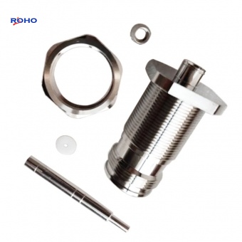
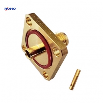
| Bulkhead | SMA female to SMA female (panel mount) | Passing signals through a panel or chassis |
| Hermetic | SMA female to SMA female (sealed) | Vacuum or high-pressure applications |
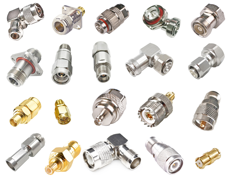
Between-Series Adapters (Different Connector Types)
These adapters connect dissimilar connector families, enabling interface conversion. They are essential for integrating equipment from different generations, vendors, or standards.
| Common Adapter Combinations | Typical Applications |
| SMA to N-Type | Test equipment to high-power components; lab to field equipment |
| SMA to BNC | Lab instruments (SMA) to general-purpose cables (BNC) |
| SMA to TNC | Lab (SMA) to vibration-resistant systems (TNC) |
| SMA to 2.92mm / 3.5mm | Precision millimeter-wave to standard SMA |
| N-Type to BNC | High-power RF (N-Type) to lab equipment (BNC) |
| N-Type to TNC | High-power (N-Type) to vibration-resistant (TNC) |
| 7/16 DIN to N-Type | Cellular infrastructure (7/16 DIN) to test equipment |
| 4.3-10 to N-Type | Modern dense cellular to legacy test setups |
| SMA to MCX / MMCX | Standard test (SMA) to compact internal connections |
| F-Type to BNC | CATV/satellite (F-Type) to lab equipment |
| 2.92mm to 3.5mm | Precision millimeter-wave inter-compatibility |
| 2.4mm to 1.85mm | Advanced millimeter-wave systems |
Gender defines the center contact configuration:
| Gender | Center Contact | Commonly Used For |
| Male (Plug) | Protruding center pin | Terminating female connectors; cable ends |
| Female (Jack) | Recessed center socket | Terminating male connectors; equipment ports |
| Reverse Polarity (RP) | Opposite center gender | Wi-Fi and consumer devices (regulatory compliance) |
Adapters are available in all gender combinations: male-to-male, female-to-female, and male-to-female.
| Configuration | Description | Primary Use |
| Straight (Inline) | Both connectors aligned axially | General-purpose, most common |
| Right-Angle | 90° bend between connectors | Tight spaces, cable routing constraints |
| Bulkhead / Panel Mount | Designed to mount through a panel | Chassis feedthroughs, test fixture panels |
| Hermetic / Sealed | Glass or ceramic seal; vacuum-tight | Aerospace, vacuum systems, high-altitude |
| Flexible | Includes a short flexible cable between connectors | Reducing stress, accommodating misalignment |
| Precision / Metrology Grade | Individually tested, lower VSWR, tighter tolerances | Calibration, high-accuracy measurement |
The materials used in an adapter determine its durability, conductivity, and environmental resistance.
| Component | Material | Characteristics |
| Body | Brass (nickel, silver, or gold plated); stainless steel; beryllium copper | Strength, conductivity, corrosion resistance |
| Center Contact | Beryllium copper or phosphor bronze; gold plated | Spring properties, low contact resistance, corrosion resistance |
| Dielectric / Insulator | PTFE (Teflon); PEI; air (precision) | Low loss, stable impedance, high dielectric strength |
| Coupling Nut | Brass with nickel plating; stainless steel | Durability, corrosion resistance, torque consistency |
| Impedance | Frequency Range | Applications |
| 50 Ω | DC – 110 GHz | Telecommunications, test, aerospace, most RF systems |
| 75 Ω | DC – 4 GHz (to 6 GHz) | Video broadcast, CATV, satellite receivers |
| Dual Impedance | Varies | Specialized adapters for specific systems |
The operating frequency range of an adapter is limited by the lower-performing connector in the combination. For example, an SMA-to-N-Type adapter is limited by the N-Type's frequency capability (typically 11–18 GHz), even though SMA can reach 18–26.5 GHz.
When selecting an RF adapter, engineers must evaluate a set of critical electrical, mechanical, and environmental parameters. The table below summarizes typical specifications for different adapter grades.
| Parameter | Standard Grade | Precision Grade | High-Frequency Grade |
| Frequency range | DC – 6 GHz | DC – 18 GHz | DC – 40 GHz (and above) |
| VSWR (typ.) | 1.3:1 – 1.5:1 | 1.15:1 – 1.25:1 | 1.10:1 – 1.20:1 |
| Insertion loss (typ.) | 0.2 – 0.4 dB | 0.05 – 0.15 dB | 0.05 – 0.10 dB |
| Impedance | 50 Ω or 75 Ω | 50 Ω | 50 Ω |
| Contact resistance center | ≤ 6 mΩ | ≤ 3 mΩ | ≤ 2 mΩ |
| Contact resistance outer | ≤ 2 mΩ | ≤ 1 mΩ | ≤ 1 mΩ |
| Insulation resistance | ≥ 5,000 MΩ | ≥ 10,000 MΩ | ≥ 10,000 MΩ |
| Dielectric withstanding voltage | 750 – 1,500 Vrms | 1,000 – 2,000 Vrms | 1,000 – 2,000 Vrms |
| Operating temperature | -40°C to +85°C | -55°C to +125°C | -55°C to +165°C |
| Mating cycle durability | 500 cycles | 500 – 1,000 cycles | 500 – 1,000 cycles |
| Shielding effectiveness | ≥ 80 dB | ≥ 90 dB | ≥ 100 dB |
Frequency Range
The maximum operating frequency of an adapter is determined by the connector with the lower frequency rating. For example, a 2.92mm (40 GHz) to SMA (18 GHz) adapter is specified only to 18 GHz, because the SMA connector cannot maintain performance beyond that point. High-quality precision adapters may push the frequency range of a connector family to its practical limit—for example, some precision N-Type adapters are rated to 18 GHz, exceeding the standard 11 GHz limit.
VSWR (Voltage Standing Wave Ratio)
VSWR is the most critical performance metric for an adapter. It measures the quality of the impedance match across the adapter. A low VSWR ensures minimal reflections and maximum power transfer.
Standard grade: VSWR ≤ 1.30:1 to 1.50:1 at frequency.
Precision grade: VSWR ≤ 1.15:1 to 1.25:1.
Metrology grade: VSWR ≤ 1.08:1 to 1.12:1 (for calibration adapters).
Adapters that transition between connector families often have slightly higher VSWR due to the unavoidable physical and electrical transitions. However, well-designed between-series adapters maintain excellent VSWR.
Insertion Loss
Insertion loss is the signal power lost as it passes through the adapter. It is caused by conductor resistance, dielectric loss, and reflections. High-quality adapters have loss below 0.1 dB at their operating frequency. Multiple adapters in cascade can accumulate significant loss, so minimizing the number of adapters in a signal path is best practice.
Contact Resistance
Low and stable contact resistance ensures reliable signal transmission and prevents heating at high currents. Gold plating on center contacts provides low and stable resistance, while silver plating offers the lowest resistance but may tarnish over time.
Passive Intermodulation (PIM)
For cellular and multi-carrier systems, PIM is a critical consideration. PIM occurs when two or more high-power signals mix at a nonlinear junction (e.g., poor contact, contamination, or ferromagnetic materials). Low-PIM adapters use non-ferromagnetic materials (brass, stainless steel), high-quality plating (silver or low-PIM nickel), and precise assembly to achieve PIM performance of –160 dBc or better.
Durability and Mating Cycles
Durability is specified as the number of mating cycles the adapter can withstand while maintaining electrical performance. Precision connectors typically have gold-plated beryllium copper contacts, which withstand 500–1,000 cycles with minimal degradation. In test environments, adapters are frequently connected and disconnected, so high cycle life is essential.
Shielding Effectiveness
Shielding effectiveness measures how well the adapter prevents signal leakage and ingress. It is determined by the connector design and housing construction. Precision adapters with fully enclosed, continuous bodies provide the best shielding.
Environmental Specifications
Operating temperature and environmental ratings are critical for outdoor and aerospace applications.
Temperature: Commercial (-40°C to +85°C), Industrial (-55°C to +125°C), Aerospace (-65°C to +165°C).
Moisture / Weather: IP-rated adapters are available for outdoor use.
Vacuum: Hermetic adapters with glass or ceramic seals for aerospace and vacuum systems.
Outgassing: Critical for space applications; connectors must meet NASA/ESA outgassing limits.
| Adapter Type | Configuration | Typical Applications |
| SMA Male to SMA Female | In-series, straight | Extending SMA cables; changing gender |
| SMA Female to N-Type Male | Between-series | Connecting lab SMA equipment to high-power N-Type cables |
| BNC Female to SMA Male | Between-series | Lab instruments (BNC) to RF test (SMA) |
| N-Type Female to 7/16 DIN Male | Between-series | Test equipment (N-Type) to cellular infrastructure (7/16 DIN) |
| 2.92mm Female to SMA Male | Between-series | Millimeter-wave equipment (2.92mm) to general test (SMA) |
| Bulkhead SMA Female to SMA Female | In-series, panel mount | Passing signals through a test fixture or equipment chassis |
| Right-Angle N-Type Male to N-Type Female | In-series, 90° | Cable routing in tight spaces |
| Hermetic SMA Female to SMA Female | In-series, sealed | Vacuum chambers, high-altitude systems |
Precision adapters are a distinct class designed for calibration and high-accuracy measurement.
| Feature | Purpose |
| Individual testing | Each adapter is tested and supplied with measured VSWR/return loss data |
| Traceable calibration | Data traceable to national metrology institutes (NIST, NPL, PTB) |
| Tighter tolerances | Machined to higher precision, lower VSWR, and more consistent performance |
| Stainless steel construction | Enhanced durability and dimensional stability |
| Gold plating | Low and stable contact resistance |
| Phase matching | For applications where multiple adapters must have equal electrical length |
Precision adapters are essential for calibration kits, vector network analyzers (VNAs), and measurement setups where accuracy and repeatability are paramount.
When specifying an RF adapter, consider the following factors:
| Factor | Guidelines |
| Connector types | Identify the interfaces on both ends; choose the appropriate adapter combination. |
| Gender | Match gender to the ports (male to female, female to male, etc.). |
| Impedance | Verify 50 Ω or 75 Ω; mismatch causes reflections and loss. |
| Frequency range | Ensure the adapter covers your highest operating frequency. |
| VSWR | Specify low VSWR for precision measurement; standard grade for general use. |
| Construction | Choose straight, right-angle, bulkhead, or hermetically sealed as needed. |
| Materials | For high-reliability or harsh environments, choose stainless steel and gold plating. |
| PIM | For multi-carrier cellular systems, specify low-PIM adapters. |
| Environmental rating | For outdoor or industrial use, verify temperature range and IP rating. |
| Mating cycles | For test environments, ensure 500+ cycle durability. |
| Adapters in series | Avoid cascading multiple adapters; each adds loss and increases VSWR. |
Common Mistakes and Troubleshooting
Impedance mismatch: Using a 50 Ω adapter in a 75 Ω system (or vice versa) introduces loss and reflections.
Incorrect gender: Ordering male-to-male when female-to-male is needed.
Over-torquing: Damages threads and connectors; always use recommended torque.
Cross-threading: Threaded connectors must be carefully aligned before tightening.
Contamination: Dirt, oil, and oxidation on contacts cause high loss and PIM; clean adapters regularly.
Exceeding frequency range: Using an adapter beyond its specified cutoff frequency causes poor VSWR and loss.
Chain too many adapters: Each adapter introduces loss and VSWR degradation; minimize the number of adapters in the signal path.
Market Trends
Higher frequencies: Adapters are being designed for frequencies up to 110 GHz (1.0mm) and beyond to support 5G mmWave, 6G, and automotive radar.
Low-PIM: Cellular multi-carrier systems demand low-PIM adapters; 4.3-10 and 7/16 DIN low-PIM adapters are increasingly common.
Miniaturization: Smaller adapters (SMB, MCX, MMCX) are gaining popularity for portable and space-constrained devices.
Precision metrology: Calibration-grade adapters with traceable data are in high demand as test requirements tighten.
Ruggedization: Adapters with enhanced durability, corrosion resistance, and IP ratings are increasingly used in outdoor and field environments.
RF adapters are the universal connectors that enable system integration, test flexibility, and equipment interoperability. By understanding their classification—in-series vs. between-series, gender configurations, construction styles, and materials—engineers can select the appropriate adapter for any interface challenge. Key performance characteristics—frequency range, VSWR, insertion loss, PIM, contact resistance, durability, and environmental robustness—define the adapter's suitability for each application.
When specifying an adapter, pay careful attention to the connector interfaces, impedance, frequency requirements, and environmental conditions. Choose high-quality adapters with gold-plated contacts, robust materials, and low VSWR to ensure signal integrity and system reliability.
As RF systems continue to diversify and advance toward higher frequencies, the humble RF adapter remains an essential tool—the universal translator that connects the disparate worlds of modern RF engineering.