

-
We’re On Call 24/7 : +8613538296050
-
E-mail : anna@rohoconnector.com
We’re On Call 24/7 : +8613538296050
E-mail : anna@rohoconnector.com
In the intricate world of radio frequency (RF) and microwave systems, the cable assembly is often the unsung hero—or the silent saboteur. While amplifiers, filters, and antennas receive considerable attention, the interconnecting cable assemblies are the vital links that can either preserve signal integrity or introduce losses, reflections, and interference that degrade system performance. As wireless networks push toward higher frequencies, data rates, and power levels, the demands on RF cable assemblies have intensified, making their selection a critical engineering decision.
This report provides a comprehensive overview of the classification and key performance characteristics of RF cable assemblies, offering essential guidance for engineers, system integrators, and procurement professionals.
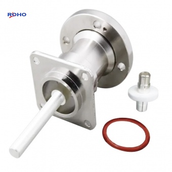
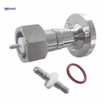
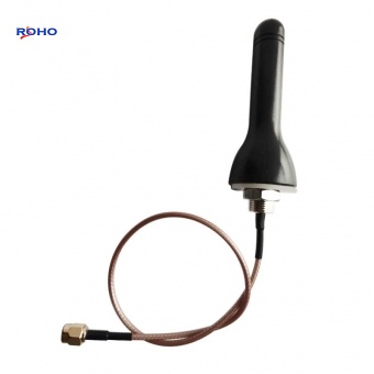
An RF cable assembly is a complete transmission line unit comprising a coaxial cable with connectors terminated at one or both ends. It is designed to transmit RF signals from one point to another while maintaining the system's characteristic impedance, minimizing signal loss, and preventing interference. Cable assemblies are used across virtually every RF application: telecommunications infrastructure, test and measurement, aerospace and defense, broadcast, medical devices, and consumer electronics.
The simplest assembly consists of:
Inner Conductor: Carries the RF signal (solid or stranded wire).
Dielectric Insulator: Separates the inner conductor from the outer shield while maintaining constant impedance.
Outer Conductor (Shield): Provides return path and electromagnetic shielding (braid, foil, or solid tube).
Jacket: Protects the cable from environmental damage (mechanical, chemical, thermal).
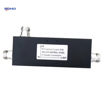
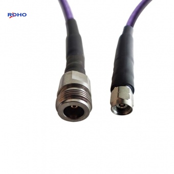
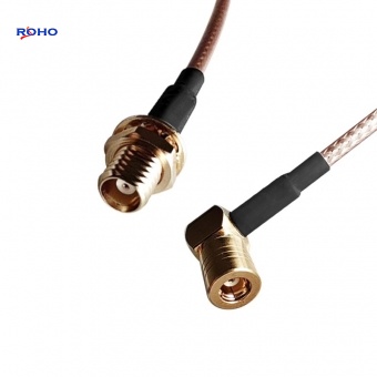
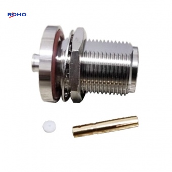
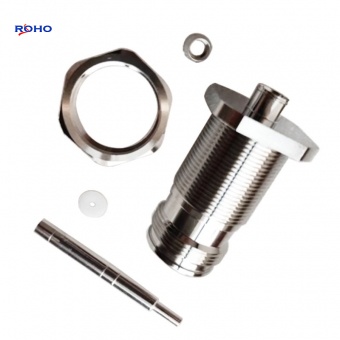
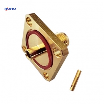
Connectors: Terminate the cable to interface with equipment (SMA, N-Type, BNC, TNC, 7/16 DIN, 4.3-10, etc.).
RF cable assemblies can be classified according to cable type, connector type, frequency range, power handling, and construction.
The cable itself is the defining component of the assembly. Cables are classified by their construction, dielectric material, and intended application.
Construction: Braided outer conductor; stranded or solid inner conductor; flexible dielectric (often PTFE, FEP, or polyethylene).
Characteristics: Easy to route and install; moderate loss; good flexibility; lower cost.
Applications: General-purpose RF connections, test leads, jumpers, patch cables.
Typical Frequency: Up to 18 GHz (some to 40 GHz).
Example: RG-58, RG-316, LMR-400, RG-174.
Construction: Solid copper or aluminum outer conductor; solid dielectric (PTFE); solid or stranded inner conductor.
Characteristics: Excellent shielding (> 100 dB); very low loss; high phase stability; high power handling; minimal flexibility (can be bent once with special tools).
Applications: High-frequency test equipment, military systems, satellite payloads, phase-critical applications.
Typical Frequency: Up to 40 GHz and beyond.
Example: UT-085, UT-141, SUCOFORM 141.
Conformable Cables
Construction: Similar to semi-rigid but with a thin-walled, slightly flexible outer conductor that allows hand bending.
Characteristics: Good shielding; moderate loss; easier to route than semi-rigid; good phase stability.
Applications: Test and measurement, compact systems where semi-rigid is too difficult to install.
Typical Frequency: Up to 40 GHz.
Ruggedized / Military Cables
Construction: Multiple braid layers; robust jacket (often polyurethane, PVC, or TPE); reinforced connectors; weatherproof sealing.
Characteristics: High durability; withstands repeated flexing, extreme temperatures, and harsh environments; often exceeds MIL-STD requirements.
Applications: Military communications, field equipment, outdoor infrastructure, aerospace.
Typical Frequency: Up to 18 GHz (some to 40 GHz).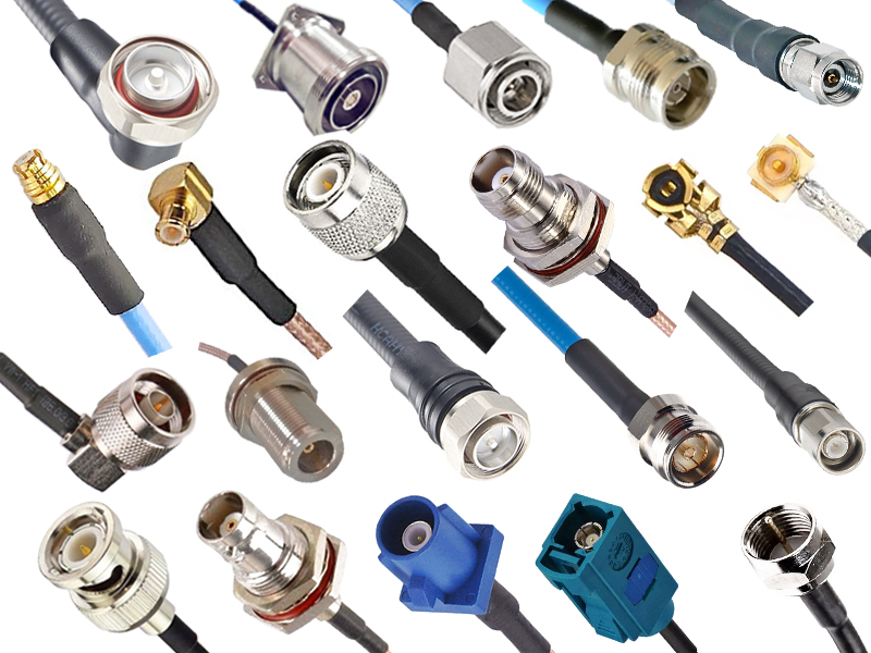
The connectors terminated on the cable determine the assembly's compatibility with equipment. Common connector families used in cable assemblies include:
| Connector Family | Frequency Range | Impedance | Key Features |
| SMA | DC – 18 GHz (up to 26.5 GHz) | 50 Ω | Compact, threaded, most common for test |
| N-Type | DC – 11 GHz (up to 18 GHz) | 50 Ω | Rugged, weatherproof, moderate power |
| BNC | DC – 4 GHz (up to 6 GHz) | 50 Ω / 75 Ω | Bayonet, quick-connect, lab standard |
| TNC | DC – 11 GHz (up to 18 GHz) | 50 Ω | Threaded BNC, vibration-resistant |
| 7/16 DIN | DC – 7.5 GHz | 50 Ω | Large, high power, low PIM |
| 4.3-10 | DC – 6 GHz | 50 Ω | Compact, high power, low PIM |
| F-Type | DC – 3 GHz (up to 6 GHz) | 75 Ω | CATV, satellite, consumer broadband |
| SMB / SMC | DC – 4 GHz (up to 10 GHz) | 50 Ω | Snap-on, compact, modular |
| MCX / MMCX | DC – 6 GHz | 50 Ω | Ultra-compact, portable devices |
| 2.92mm (K) | DC – 40 GHz | 50 Ω | Precision, high-frequency |
| 2.4mm | DC – 50 GHz | 50 Ω | Very high-frequency, precision |
| 1.85mm | DC – 67 GHz | 50 Ω | Sub-millimeter wave, advanced research |
| 1.0mm | DC – 110 GHz | 50 Ω | Highest frequency, terahertz research |
Connector gender (male/plug or female/jack) must match the equipment port. Cable assemblies may have the same connector on both ends (straight-through) or different connectors (adapters) for interface conversion.
Cable assemblies are designed for specific frequency bands:
| Category | Frequency Range | Cable Types | Typical Applications |
| Low-frequency | DC – 1 GHz | Flexible (RG-58, RG-59) | Audio, video, CATV, legacy radio |
| Microwave | 1 – 18 GHz | Flexible, semi-rigid, conformable | Cellular, Wi-Fi, radar, test |
| Millimeter-wave | 18 – 40 GHz | Semi-rigid, precision flexible | 5G mmWave, satellite, defense |
| Sub-millimeter | 40 – 110 GHz | Semi-rigid (1.85mm, 1.0mm) | Advanced research, 6G, terahertz |
For applications requiring precise phase relationships (phased arrays, coherent systems, interferometers), phase-stable assemblies are essential.
Standard: Good phase stability for general use.
Phase-Stable (low-loss): Designed for phase-sensitive applications; often includes helically wrapped or specialized dielectrics.
Phase-Matched Sets: Multiple cable assemblies are cut to the same electrical length (or phase) to ensure coherent signal distribution.
Temperature-Phase-Stable: Maintains phase over wide temperature ranges; critical for outdoor and aerospace systems.
Shielding effectiveness quantifies how well the cable prevents external signals from interfering with the internal signal (ingress) and prevents internal signals from radiating (egress).
| Shield Type | Shielding Effectiveness (Typical) | Characteristics |
| Single Braid | 40–50 dB | Basic, low-cost, flexible |
| Double Braid | 50–70 dB | Good shielding, moderate flexibility |
| Foil + Braid | 70–90 dB | Excellent shielding, common in CATV |
| Solid Tube (semi-rigid) | > 100 dB | Superior shielding, inflexible |
The performance of an RF cable assembly is defined by several critical electrical, mechanical, and environmental parameters. The table below summarizes typical specifications for different cable assembly grades.
| Parameter | Standard Grade | High-Performance Grade | Precision Grade |
| Frequency range | DC – 18 GHz | DC – 26.5 GHz | DC – 40+ GHz |
| Insertion loss (typ., per meter) | 0.5–1.0 dB at 18 GHz | 0.3–0.6 dB at 26.5 GHz | 0.2–0.4 dB at 40 GHz |
| VSWR (typ.) | ≤ 1.3:1 | ≤ 1.25:1 | ≤ 1.15:1 |
| Shielding effectiveness | > 80 dB | > 90 dB | > 100 dB |
| Phase stability vs. flexure | ±3° at 18 GHz | ±2° at 26.5 GHz | ±1° at 40 GHz |
| Phase stability vs. temperature | ±5° at 18 GHz | ±3° at 26.5 GHz | ±2° at 40 GHz |
| Power handling (typ.) | 50–100 W | 30–50 W | 5–20 W |
| Operating temperature | -40°C to +85°C | -55°C to +125°C | -55°C to +165°C |
| Mating cycle durability | 500 cycles | 500 cycles | 1,000 cycles |
| Impedance | 50 Ω or 75 Ω | 50 Ω | 50 Ω |
1. Insertion Loss
Insertion loss is the signal power lost as it passes through the cable assembly, expressed in decibels per unit length (dB/m or dB/ft). Loss is caused by conductor resistance (skin effect), dielectric absorption, and reflections. At higher frequencies, skin effect increases conductor loss significantly, so cable assemblies designed for millimeter-wave use very small-diameter, high-quality cables with low-loss dielectrics.
For a typical system, total insertion loss is the sum of cable loss plus connector loss. Connector loss is typically 0.05–0.15 dB per connector at lower frequencies, increasing at higher frequencies.
2. VSWR (Voltage Standing Wave Ratio)
VSWR measures the impedance match of the cable assembly. A low VSWR ensures maximum power transfer and minimal reflections. Cable assembly VSWR is determined by:
Connector impedance match
Cable impedance uniformity
Termination quality (the interface between cable and connector)
A high-quality cable assembly achieves VSWR of 1.25:1 or better across its frequency range. Precision assemblies achieve 1.15:1 or better.
3. Shielding Effectiveness
Shielding effectiveness is critical for preventing interference in dense RF environments. It is measured in decibels (dB) and indicates how much the cable attenuates external signals. Poor shielding leads to:
Ingress: External signals (cellular, Wi-Fi, broadcast) coupling into the cable, causing interference.
Egress: Internal signals leaking out, potentially interfering with other equipment or violating regulatory limits.
Semi-rigid cables provide the highest shielding effectiveness (> 100 dB) because the solid metal tube acts as a continuous shield. Braided cables, depending on coverage percentage, provide 40–70 dB.
4. Phase Stability
Phase stability is the ability of the cable assembly to maintain its electrical length (and thus phase) under mechanical and thermal stress.
Phase vs. Flexure: How much phase changes when the cable is bent or moved. Critical for test leads and moving systems.
Phase vs. Temperature: How much phase changes with temperature. Critical for outdoor and aerospace systems.
Phase-Matched Assemblies: Multiple cables cut to the same phase length for coherent systems.
Phase-stable cables use specialized dielectrics (e.g., low-density PTFE) and construction techniques (helically wrapped tape) to minimize phase changes.
5. Power Handling
Power handling is limited by the cable's ability to dissipate heat without dielectric breakdown. It depends on:
Cable size: Larger cables handle more power.
Frequency: Power handling decreases at higher frequencies due to skin effect losses.
Ambient temperature: Derating curves apply at elevated temperatures.
Altitude: Reduced air pressure lowers breakdown voltage, reducing peak power handling.
6. Environmental Durability
Cable assemblies must withstand their operating environment:
Temperature range: From -65°C to +165°C for aerospace/military; -40°C to +85°C for outdoor telecom; 0°C to +70°C for indoor lab.
Flex life: How many flex cycles the cable withstands without degradation (for portable/test applications).
UV and weather resistance: Jackets (PVC, PE, TPE) and connector plating must resist sun, rain, and salt spray.
Chemical resistance: For industrial environments (oil, solvents, cleaning agents).
7. Cable Construction Details
| Parameter | Typical Values | Impact |
| Conductor material | Copper, silver-plated copper, copper-clad steel | Lower loss, better conductivity |
| Dielectric | PTFE, FEP, PE, expanded PTFE | Lower loss, stable impedance, phase stability |
| Shield type | Braid, foil, solid tube, or combinations | Shielding effectiveness, flexibility |
| Jacket | PVC, PE, polyurethane, silicone, PTFE | Environmental protection, flexibility |
RF cable assemblies are used in almost every sector of the RF industry:
| Application | Cable Type | Connector Types | Key Requirements |
| Test & Measurement | Flexible, phase-stable | SMA, N-Type, 2.92mm, BNC | Low loss, low VSWR, high repeatability |
| Cellular Base Stations | Low-loss, low-PIM flexible | 7/16 DIN, 4.3-10, N-Type | Low PIM, high power, weatherproof |
| Aerospace & Defense | Semi-rigid, ruggedized | SMA, N-Type, TNC, SHV | Wide temperature, vibration, MIL-STD |
| Satellite Payloads | Semi-rigid, low-outgassing | SMA, 2.4mm, 1.85mm | Low outgassing, phase stability, vacuum |
| Broadcast & CATV | Flexible 75 Ω | BNC, F-Type, RCA | Low loss, low cost, 75 Ω impedance |
| Medical Devices | Flexible, sterilizable | SMA, BNC, SMB | Sterilization compatibility, reliability |
| Automotive | Ruggedized | FAKRA, SMA | Vibration tolerance, compact size |
| Consumer Electronics | Low-cost flexible | BNC, F-Type, SMA | Low cost, ease of use |
Selection Guidelines for Engineers
| Factor | Considerations |
| Frequency | Ensure the assembly's specified frequency range covers the highest operating frequency, including harmonics if testing nonlinear devices. |
| Impedance | Verify 50 Ω for RF/telecom, 75 Ω for video/CATV. Use matching connectors. |
| Connector type | Match to equipment ports; consider adapter requirements if interfaces differ. |
| Cable type | Choose flexible for test/portable; semi-rigid for fixed, phase-critical; ruggedized for outdoor/field. |
| VSWR / Return loss | For precision measurement, specify low VSWR (≤ 1.20:1). For general use, ≤ 1.30:1 may suffice. |
| Phase stability | Specify phase-stable cables for moving systems or phase-sensitive applications; consider phase-matched sets. |
| Power handling | Calculate average and peak power; choose an assembly with 20–30% safety margin. Apply derating for elevated temperatures. |
| Length | Specify accurately; longer cables add loss; avoid unnecessary length. |
| Environmental conditions | Consider temperature, moisture, vibration, and chemical exposure. Specify IP rating or MIL-STD compliance. |
| Mating cycles | For test environments with frequent connections, ensure connector durability (500+ cycles) and robust materials. |
| Cost | Balance performance with budget; precision cables and custom assemblies are more expensive than standard off-the-shelf. |
Avoid sharp bends: Exceed the cable's minimum bend radius to prevent damage or performance degradation.
Support cables: Use cable ties and strain relief to prevent mechanical stress on connectors.
Use proper torque: Threaded connectors require specific torque (e.g., SMA 0.7–0.9 Nm; N-Type 1.0–1.5 Nm). Over-torquing damages connectors; under-torquing causes high VSWR and PIM.
Keep connectors clean: Contamination (dirt, oil, oxidation) increases insertion loss and causes PIM. Use appropriate cleaning tools and procedures.
Label cables: For complex systems, label both ends for identification and to prevent misconnections.
Inspect periodically: Check for damage to the jacket, connectors, and shielding; test VSWR and insertion loss as part of preventive maintenance.
Several trends are shaping the RF cable assembly market:
Higher frequencies: 5G mmWave (28–39 GHz), 6G (100 GHz+), and automotive radar (77–81 GHz) are driving demand for precision cable assemblies with extremely low loss and high phase stability.
Low-PIM: As cellular networks densify and add carriers, low-PIM cable assemblies (using 4.3-10, 7/16 DIN, and low-PIM N-Type) are essential.
Test and measurement: Increasingly complex systems require more test leads and custom cable assemblies for automated and high-volume testing.
Ruggedization: Military, aerospace, and industrial applications demand cable assemblies that withstand extreme temperatures, vibration, and water ingress.
Phase-matched assemblies: For massive MIMO and phased arrays, matched-phase cable assemblies are becoming standard.
RF cable assemblies are the backbone of any RF system, transmitting signals between equipment with minimal loss and interference. Their classification by cable type, connector type, frequency range, and construction provides a framework for selection, while key performance characteristics—insertion loss, VSWR, shielding effectiveness, phase stability, power handling, and environmental durability—define their suitability for each application.
When specifying a cable assembly, engineers must balance frequency, impedance, connectors, length, power, environment, and cost. The right cable assembly, correctly installed and maintained, will preserve signal integrity, reduce system failures, and ensure reliable operation over years of service.
As wireless systems continue to advance toward higher frequencies and greater complexity, RF cable assemblies will remain essential components—the critical links that connect the future of communications.