

-
We’re On Call 24/7 : +8613538296050
-
E-mail : anna@rohoconnector.com
We’re On Call 24/7 : +8613538296050
E-mail : anna@rohoconnector.com
In the era of gigabit broadband, streaming video, and smart home connectivity, one humble component quietly enables the entire cable television and data infrastructure: the CATV splitter. Often overlooked by consumers yet essential to network performance, these passive devices are responsible for distributing high‑frequency signals from a single cable drop to multiple outlets, set‑top boxes, cable modems, and other customer premises equipment. As operators upgrade networks to support DOCSIS 3.1, 4.0, and beyond, the demands on CATV splitters have never been greater.
This report examines the classification and key performance characteristics of CATV splitters, providing technical insights for network engineers, installers, and system integrators.
A CATV (Community Antenna Television) splitter is a passive RF device that takes one input signal (typically from a cable provider’s drop or a distribution amplifier) and divides it into two or more output signals, each carrying the same frequency content but at reduced power. Splitters are the fundamental building blocks of coaxial home and business networks, enabling multiple TVs, modems, and other devices to share a single cable connection.
CATV splitters are designed for 75‑ohm impedance, the standard for video, broadband, and satellite systems, and typically operate over a frequency range extending from 5 MHz to 1002 MHz, 1218 MHz, 1670 MHz, or even 3 GHz for next‑generation networks. Modern splitters must support bidirectional communication: downstream (from the network to the subscriber) and upstream (from the subscriber’s cable modem back to the network).
CATV splitters are classified by port configuration, frequency range, insertion loss, isolation, and environmental design.
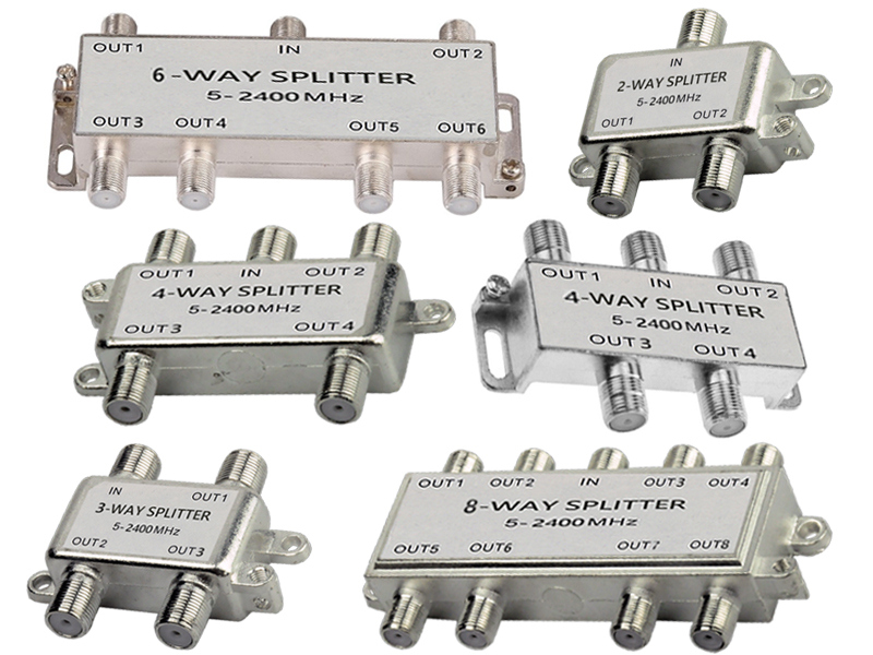
The number of output ports is the most obvious classification, ranging from simple 2‑way splits to complex 8‑way or 16‑way distribution hubs.
| Port Count | Typical Applications | Theoretical Split Loss |
| 2‑way | Basic residential splits (e.g., feeding a modem and one TV) | 3.0 dB |
| 3‑way | Uneven distribution (often one low‑loss port + two higher‑loss ports) | 4.8 dB (equal split) |
| 4‑way | Multiple rooms, small businesses | 6.0 dB |
| 6‑way | Larger residences, small MDUs (multi‑dwelling units) | 7.8 dB |
| 8‑way | Apartment buildings, commercial installations | 9.0 dB |
| 16‑way | Head‑end distribution, large MDUs | 12.0 dB |
Unequal (Tapped) Splitters: Some 3‑way and 4‑way splitters are designed with one "through" port having lower loss (e.g., 3.5 dB) and two or three "tap" ports with higher loss (e.g., 7 dB). This allows a cable modem to be connected to the low‑loss port while TV set‑top boxes use the higher‑loss ports, preserving signal quality for the most critical device.
As cable networks evolve, splitter bandwidth has expanded significantly.
Legacy (5–860 MHz): Supports analog TV and early digital cable.
Standard (5–1002 MHz): Covers most DOCSIS 3.0 deployments.
Extended (5–1218 MHz): Required for DOCSIS 3.1 (up to 1.2 GHz downstream).
Ultra‑wide (5–1670 MHz / 5–1800 MHz / 5–3000 MHz): For DOCSIS 4.0 (1.8 GHz), satellite IF distribution, and emerging broadband standards.
Splitters must also pass the upstream return path (typically 5–42 MHz in North America, 5–65 MHz in Europe, or 5–85 MHz/5–204 MHz for DOCSIS 4.0). Modern splitters are thus "bi‑directional" (or "5–XXXX MHz" rated).
While 75 Ω is universal for CATV, a small number of 50 Ω splitters exist for certain test or legacy RF systems. CATV splitters are never interchangeable with 50 Ω equipment without causing mismatch losses.
CATV splitters vary in quality and price. They are often informally classified as:
Economy / Consumer grade: Low‑cost units with modest isolation (10–15 dB) and average return loss. Suitable for simple, short‑run residential installations with few channels.
Premium / Professional grade: Higher isolation (20–25 dB), better return loss (≥ 16–18 dB), and flat frequency response. Used by cable operators and in MDUs.
Active splitters (distribution amplifiers): Not strictly passive splitters, but worth noting. These include an internal amplifier to overcome split loss, used when signals are very weak or many outlets are needed.
Indoor splitters: Unsealed plastic or metal housings, designed for conditioned spaces.
Outdoor / Weatherproof splitters: Die‑cast metal housings with gasketed covers and corrosion‑resistant connectors (often F‑type with nickel or gold plating). Rated for direct sunlight, moisture, and temperature extremes.
MoCA‑optimized splitters: Designed to pass MoCA (Multimedia over Coax Alliance) frequencies (extending to 1675 MHz or higher) with minimal insertion loss and high port‑to‑port isolation to prevent interference between MoCA nodes.
The table below summarizes typical specifications for a modern high‑performance CATV splitter covering 5–1218 MHz.
| Parameter | Typical Specification | Notes |
| Frequency range | 5–1218 MHz (or 5–1670 MHz, 5–3000 MHz) | Must cover both downstream and upstream bands |
| Insertion loss (2‑way) | 3.5–4.0 dB (including split loss + excess loss) | Theoretical minimum 3.0 dB |
| Insertion loss (4‑way) | 7.0–7.5 dB | Theoretical minimum 6.0 dB |
| Isolation (port to port) | ≥ 20 dB (typical 25–30 dB at mid‑band) | Critical to prevent crosstalk between devices |
| Return loss | ≥ 16 dB (typically 18–20 dB) | Indicates impedance match; higher is better |
| Impedance | 75 Ω | Fixed |
| Shielding effectiveness | ≥ 85 dB (often > 100 dB) | Prevents ingress/egress of interference |
| Insertion loss flatness | ±0.5 dB over frequency range | Prevents signal tilt |
| DC pass capability | Typically all ports pass DC (for powering amplifiers) | Some splitters block DC on specific ports |
| Operating temperature | –40°C to +85°C (outdoor models) | Indoor models –10°C to +50°C |
| Connector type | F‑type female (75 Ω) | Most common; some use BNC or RCA for older equipment |
Insertion Loss
This is the signal power lost from input to any output. For a 2‑way splitter, the theoretical minimum is 3.0 dB (half the power to each port). Real‑world units have additional losses due to transformer inefficiency, PCB traces, and connector losses. A good 2‑way splitter achieves 3.5–3.8 dB at mid‑frequencies; cheap units may exceed 4.5 dB. Higher losses mean weaker signals to modems and set‑top boxes, potentially causing errors or dropped channels.
Isolation
Isolation measures how much of a signal present on one output port appears on another output port. Low isolation causes crosstalk: for example, a cable modem’s upstream transmission could interfere with a nearby TV tuner, or two modems could "hear" each other, disrupting time‑division multiple access (TDMA) protocols. Premium splitters provide 20–30 dB isolation. Higher frequency bands (e.g., 1 GHz) typically have lower isolation than lower bands, so quality units are designed to maintain isolation across the entire range.
Return Loss
Return loss indicates how well the splitter matches the 75 Ω impedance. Low return loss (e.g., 10 dB) means significant signal reflections, which cause ghosting in analog video and bit errors in digital streams. Good CATV splitters maintain return loss of at least 16 dB (preferably 20 dB) across all ports and frequencies. This is especially important for the upstream path, where reflections can confuse a cable modem’s ranging algorithms.
Shielding Effectiveness
Because CATV splitters are often located near other electronics (TVs, computers, power supplies), they must be well‑shielded to prevent external interference from entering the cable system (ingress) and to prevent cable signals from radiating (egress). High‑quality splitters use die‑cast zinc or aluminum housings with RF gaskets, achieving shielding effectiveness > 85 dB (often > 100 dB). Cheap plastic‑housed splitters provide little shielding and can ruin network performance.
Frequency Response Flatness
The insertion loss should not vary wildly across the operating bandwidth. Poor flatness (e.g., ±1.5 dB) can "tilt" the signal, making high‑frequency channels (e.g., 1 GHz) much weaker than low‑frequency channels. Modern splitters achieve ±0.5 dB or better flatness, ensuring consistent performance across all channels.
DC Pass
Many cable systems use the coaxial cable to power remote amplifiers or optical nodes. A splitter may be designed to pass DC current (typically up to 1 A) from the input port to one or more output ports, while blocking DC on other ports. This feature is marked on the splitter housing (e.g., "DC Pass" or "Power Pass" on specific ports).
MoCA Compatibility
MoCA (Multimedia over Coax Alliance) technology uses frequencies above 1 GHz (typically 1125–1675 MHz) to create a home Ethernet‑over‑coax network. A standard CATV splitter may have high insertion loss or poor isolation in this band, breaking MoCA performance. MoCA‑rated splitters are designed to pass these frequencies with low loss and maintain isolation to prevent MoCA signals from leaking between ports.
When choosing a CATV splitter, consider the following factors:
| Factor | Recommendation |
| Frequency range | Match the highest frequency of your service (e.g., 1002 MHz for DOCSIS 3.0, 1218 MHz for DOCSIS 3.1, 1670+ MHz for DOCSIS 4.0 or satellite). |
| Port count | Use the minimum number of splits necessary. Every split adds loss. For unused ports, terminate with a 75‑ohm terminator (cap). |
| Isolation | For homes with multiple cable modems or MoCA networks, choose splitters with ≥ 20 dB isolation. |
| Return loss | Look for ≥ 16 dB (or ≥ 18 dB for premium). Cheap splitters often have poor return loss. |
| Shielding | Prefer die‑cast metal housings. Avoid plastic‑encased splitters. |
| MoCA support | If using MoCA adapters, select a splitter explicitly rated for MoCA (5–1675 MHz or higher). |
| Environment | Outdoor installations require weatherproof splitters with gaskets and corrosion‑resistant connectors. |
| DC pass | Verify which ports need to pass power (e.g., for an external amplifier or powered remote device). |
Under‑terminating: Leaving output ports open (unterminated) causes reflections that degrade performance for all devices. Use 75‑ohm terminators.
Chaining too many splitters: Each split adds loss. Instead, use a single larger splitter (e.g., a 4‑way rather than three 2‑way splitters in series), which typically has lower total loss and better isolation.
Ignoring return path: Upstream signals are low frequency (5–42/65 MHz). Cheap splitters may have poor return loss at low frequencies, causing modem dropouts.
Using indoor splitters outdoors: Moisture ingress corrodes connectors and internal PCBs, raising insertion loss and creating intermittent connections.
The cable industry is not standing still. Several trends are shaping the next generation of CATV splitters:
DOCSIS 4.0 (Full Duplex / Extended Spectrum): Operating up to 1.8 GHz downstream and 684 MHz upstream (or 204 MHz for FDX), splitters must maintain low loss and high isolation to 1.8 GHz and beyond. Many new models are rated to 3 GHz.
Remote PHY and fiber deep: As fiber extends closer to homes, the remaining coax segments are shorter. Splitters in these "fiber‑to‑the‑last‑amplifier" networks still need to pass high frequencies but may face different power and isolation requirements.
Integrated home networking: Splitters are increasingly combined with MoCA filters, PoE (Point of Entry) filters, or even small amplifiers in a single housing.
Higher shielding requirements: With increasing wireless interference (5G, Wi‑Fi 6E/7), shielding effectiveness standards are being raised to > 100 dB.
Self‑install kits: Operators now provide subscribers with pre‑packaged splitters that are optimized for their specific service levels (e.g., a 2‑way splitter with one low‑loss port for the modem).