

-
We’re On Call 24/7 : +8613538296050
-
E-mail : anna@rohoconnector.com
We’re On Call 24/7 : +8613538296050
E-mail : anna@rohoconnector.com
1. Power/level (dBm): the output capability of the amplifier, the general unit is w, mw, dBm
Note: dBm is an absolute power level expressed in decibels with 1mw as the reference value. Conversion formula:
Level (dBm)=10lgw
5W → 10lg5000=37dBm
10W → 10lg10000=40dBm
20W → 10lg20000=43dBm
It is not difficult to see from the above that every time the power is doubled, the level value increases by 3dBm
2. Gain (dB): the magnification factor, and the unit can be expressed in decibels (dB), That is: dB=10lgA (A is the power amplification multiple)
3. Insertion loss: the attenuation increased when a certain device or component is connected to the transmission circuit, and the unit is expressed in dB.
4. Selectivity: Measure the gain in the working frequency band and the suppression ability of out-of-band radiation. The -3dB bandwidth is the bandwidth when the gain is reduced by 3dB, and the same applies to -40dB and -60dB.
5. Standing wave ratio (return loss): the ratio of the antinode voltage to the node voltage (VSWR) in the traveling standing wave state
6. Third-order intermodulation: If there are two sinusoidal signals ω1 and ω2, many intermodulation components will be generated due to nonlinear effects. The two frequency components of 2ω1-ω2 and 2ω2-ω1 are called third-order intermodulation components. The ratio of the power of P3 and the signal ω1 or ω2 is called the third-order intermodulation coefficient M3, That is, M3 =10lg P3/P1 (dBc)
7. Noise figure: Generally defined as the ratio of output signal-to-noise ratio to input signal-to-noise ratio, which is calculated in decibels in actual use. The unit is dB.
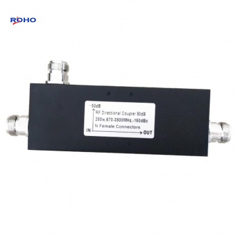
8. Coupling degree: the power ratio between the coupling port and the input port, in dB.
9. Isolation: The ratio of the power of the local oscillator or signal leaking to other ports to the original power, in dB.
10. Antenna gain (dB): Refers to the ability of an antenna to concentrate its transmission power in a certain direction. Generally, the field strength E in the maximum radiation direction of the antenna is compared with the uniform radiation field strength E0 of an ideal isotropic antenna, and the multiple of the increase in power density is defined as the gain.
11. Antenna pattern: It is the range of electromagnetic waves radiated by the antenna in free space. The width of the directional pattern generally refers to the angle between the two points when the width of the main lobe drops half from the maximum value.
The E-plane pattern refers to the in-plane radiation pattern parallel to the electric field;
The H-plane pattern refers to the in-plane radiation pattern parallel to the magnetic field.
Generally, the wider the pattern, the lower the gain; the narrower the pattern, the higher the gain.
12. Antenna front-to-rear ratio: refers to the ratio of the maximum forward gain to the maximum reverse gain, expressed in decibels.
13. Simplex: also known as single-frequency simplex system, that is, the same frequency is used for receiving and sending. Since receiving and sending use the same frequency, the receiving and sending cannot be performed at the same time, which is called simplex.
14. Duplex: also known as inter-frequency duplexing system, that is, two different frequencies are used for receiving and sending, and either party can receive the other party's speech while making a speech, Both simplex and duplex belong to the working mode of mobile communication.
15. Amplifier: (amplifier) a circuit used to achieve signal amplification.
16. Filter: (filter) a component or device that suppresses useless frequency signals through useful frequency signals
17. RF Attenuator: (attenuator) A four-terminal network composed of resistive elements whose phase shift is zero in a fairly wide frequency range and whose attenuation and characteristic impedance are constants independent of frequency. Its main purpose is to adjust Signal size in the circuit and improved impedance matching.
18. Power divider: a device for power distribution. There are two, three, four.... Power dividers; connector types are divided into N head (50Ω), SMA head (50Ω), and F head (75Ω). Our company commonly uses N head and SMA head.
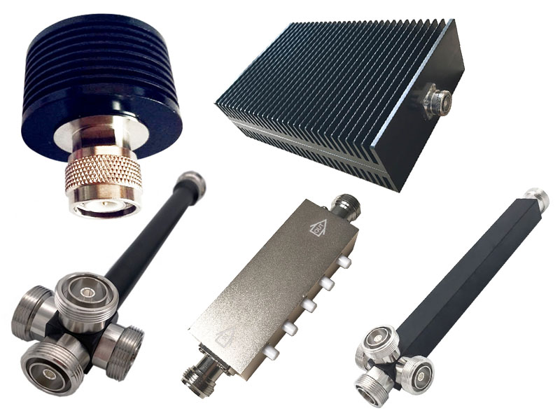
19. Coupler: A device that extracts part of the signal from the main channel. According to the coupling degree, it can be divided into 5, 10, 15, 20.... dB different specifications; high-power coupler (300W) can be used to extract the signal from the base station, and the coupling degree can be selected from 30~65dB; the connector of the coupler is mostly N head.
20. Load: The components/devices, components or devices that receive electric power at the terminal in a certain circuit (such as an amplifier) or electrical output port are collectively referred to as a load. The most basic requirements for the load are impedance matching and the power it can withstand.
21. Circulator: a device that transmits signals in one direction.
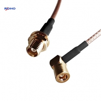
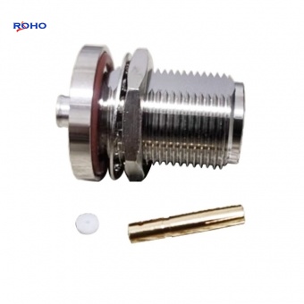
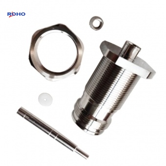
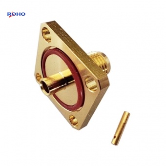
22. Adapter: a device that connects different types of transmission lines together.
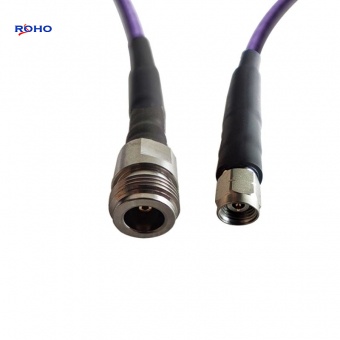
23. Feeder: It is a transmission line that transmits high-frequency current.
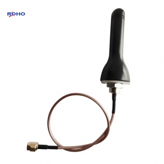
24. RF Antenna: (antenna) converts high-frequency current or energy in the form of waveguides into electromagnetic waves and emits them in a specified direction or restores electromagnetic waves from a certain direction to high-frequency currents