

-
We’re On Call 24/7 : +8613538296050
-
E-mail : anna@rohoconnector.com
We’re On Call 24/7 : +8613538296050
E-mail : anna@rohoconnector.com
The IPEX connector family—also widely known as MHF—is the default board-level RF interface for compact wireless devices, from Wi-Fi routers and wearables to 5G modules and millimeter-wave radios. But the connector alone does not determine performance. The micro-coaxial cable it terminates is equally decisive: the wrong cable diameter can compromise shielding, strain the solder joint, or introduce losses that erase the link budget gains the connector was meant to deliver.
Industry selection guidance consistently frames the problem in two dimensions. The first is the crimp barrel or termination cavity of the plug: if the cable is too thick, the rear of the connector cannot close and the shield is not fully captured; if it is too thin, the crimp lacks pull strength and long-term reliability suffers. The second is the electrical trade-off: finer cable (such as 0.81 mm outer diameter) offers superior flexibility for miniature enclosures but carries higher attenuation, while thicker cable (such as 1.37 mm) delivers lower loss at the cost of stiffness and greater mechanical stress on small PCB pads.
This report reviews the coaxial cable families most commonly paired with each IPEX/MHF generation, providing a practical reference for engineers navigating the increasingly narrow gap between connector geometry and cable reality.
First and Second Generation: The Broad-Compatibility Baseline
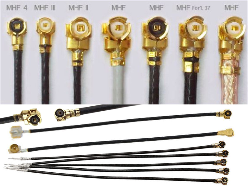
The first-generation MHF1 and its lower-profile MHF2 sibling are the most forgiving members of the family in terms of cable choice. MHF1 is widely paired with 1.13 mm, 1.32 mm, and 1.37 mm outer-diameter cables, with common cable designations including RG178, RG113, and RG137. These are mature, broadly available micro-coaxial constructions that balance flexibility and loss for applications below roughly 6 GHz.
MHF2 narrows the practical cable window to 1.13 mm and 1.32 mm, reflecting its reduced mated height and tighter mechanical envelope. In both generations, the cable diameters are large enough to be handled in volume assembly without extreme process control, which is why MHF1 remains the mechanically interchangeable counterpart to the long-standing U.FL interface and continues to appear in routers, industrial terminals, and legacy network cards.
Third Generation: The Transition to Finer Cable
The MHF3 generation represents the point at which the IPEX family begins to demand a different class of cable. Its reduced terminal geometry is optimized for 0.81 mm outer-diameter micro-coaxial cable, often described generically as “superfine” or RG081-type cable. Some sources also cite 0.64 mm cable as compatible with MHF3-class interfaces.
The shift to 0.81 mm is not cosmetic. It enables the lower mated height and smaller footprint that MHF3 was designed to achieve, but it also raises the bar for termination quality. The center conductor is finer, the dielectric is thinner, and the shield coverage is more delicate. For Wi-Fi 6 and sub-6 GHz 5G front ends, the electrical performance of a well-terminated 0.81 mm cable is adequate; the risk lies in process consistency, not in the interface concept.
Fourth Generation: A Wider Cable Palette at Higher Frequency
MHF4 and its extended-performance variant, MHF4L, are the most cable-diverse members of the family in practical use. The standard MHF4 plug is specified for 0.81 mm (AWG 36) cable, but the 4L variant—which is intermateable with MHF4 and extends usable frequency to 12 GHz—supports a considerably broader range: AWG 30 (1.37 mm), AWG 32 (1.13 mm), AWG 33 (0.95 mm), AWG 36 (0.81 mm), and AWG 36 (0.64 mm).
This breadth is why MHF4 appears across such different product classes. A 1.13 mm cable is often chosen for M.2 modules and compact 5G sub-6 radios where a balance of loss and routability is required. A 0.81 mm or 0.64 mm cable serves ultra-thin wearables and densely populated modules where z-height is the binding constraint. The official electrical data makes the cable-dependent performance explicit: at 9–12 GHz, MHF4L maintains VSWR below 1.6 with 1.37 mm cable but rises to 1.9 with 0.64–1.13 mm cable, a direct illustration of how the cable, not the connector shell alone, sets the high-frequency limit.
Fifth Generation: Millimeter-Wave Pushes Cable to the Limit
MHF5 and MHF5L push the family into the frequency region where cable loss becomes the dominant design variable. The standard MHF5 supports 0.81 mm (AWG 36), 0.64 mm (AWG 36), and 0.48 mm (AWG 38) cable, with the 0.48 mm option representing one of the finest practical micro-coaxial constructions in volume RF assemblies. MHF5L, which extends to 15 GHz, is commonly paired with 1.13 mm (AWG 32) and 0.81 mm (AWG 33) cable, trading the absolute minimum diameter for a somewhat more robust assembly.
The generational pattern is clear: as the connector moves toward millimeter-wave and high-band 5G applications, the cable menu narrows and the tolerance window tightens. A 0.48 mm cable can serve a 1.0 mm mated-height MHF5 interface, but it demands assembly processes that many production lines are not equipped to sustain. The practical engineering decision is therefore not simply “choose the smallest cable the connector accepts,” but rather “choose the largest cable the mechanical envelope allows, consistent with the frequency and loss targets.”
| IPEX / MHF Generation | Typical Mated Height | Common Compatible Cable O.D. | Representative Cable AWG |
| MHF1 | 2.5 / 3.0 mm | 1.13, 1.32, 1.37 mm | 26–32 AWG |
| MHF2 | ~2.0 mm | 1.13, 1.32 mm | 32 AWG class |
| MHF3 | ~1.5 mm | 0.81, 0.64 mm | 34–36 AWG |
| MHF4 | 1.2–1.4 mm | 0.81 mm (standard); 0.64–1.37 mm (4L) | 30–36 AWG |
| MHF5 | 1.0 mm | 0.81, 0.64, 0.48 mm | 36–38 AWG |
| MHF5L | 1.3 mm | 1.13, 0.81 mm | 32–33 AWG |
Sources: cross-referenced from industry selection guides and connector datasheets.
Selection Considerations Beyond Diameter
Cable diameter is the first filter, but it is not the only one. Three additional factors routinely determine whether an IPEX assembly succeeds in production.
Impedance consistency is non-negotiable. All IPEX/MHF generations are 50-ohm interfaces, and the cable must present the same characteristic impedance across its length. A cable that is nominally 50 ohms but varies in dielectric concentricity will produce reflections that no connector quality can compensate for.
Shielding and PIM matter more as frequencies rise. At sub-6 GHz, a well-made single-braid micro-coax is generally sufficient. At 12–15 GHz, shield coverage, dielectric loss tangent, and termination quality all become first-order contributors to insertion loss and VSWR. For multi-carrier or low-PIM-sensitive radios, the cable assembly—not just the connector—must be specified as a low-PIM component.
Assembly method is the hidden variable. Many MHF3, MHF4, and MHF5 products are designed for solderless termination technologies, which reduce thermal risk to the fine dielectric and improve repeatability. But solderless termination still depends on precise strip dimensions and controlled crimp force. A cable that is electrically ideal on paper can fail in the field if the termination process is not matched to its construction.
The Bottom Line
The IPEX connector family is often discussed as a connector selection problem. In practice, it is a connector-and-cable co-selection problem. MHF1 and MHF2 live comfortably with 1.13–1.37 mm cable. MHF3 marks the entry into 0.81 mm territory. MHF4 offers the widest practical palette, from 1.37 mm down to 0.64 mm, with performance explicitly tied to the chosen cable at the high end of its band. MHF5 and MHF5L push into 0.48–1.13 mm cable, where the frequency ceiling and the manufacturing tolerance window meet.