


-
We’re On Call 24/7 : +8613538296050
-
E-mail : anna@rohoconnector.com
We’re On Call 24/7 : +8613538296050
E-mail : anna@rohoconnector.com
If you've ever worked with RF systems, high-power amplifiers, or even complex power supplies, you've likely encountered a critical but often overlooked component: the dummy load. This unassuming device is a cornerstone of electronic testing, acting as a silent guardian that protects expensive equipment and ensures accurate measurements.
But what exactly is a dummy load, and why is it so indispensable? In simple terms, a dummy load is an electronic device or component used to simulate a real electrical load for testing purposes. Unlike the actual load (like an antenna or speaker), it is designed to absorb and dissipate power without performing any real work. Think of it as a shock absorber for your electronic circuits.
This article will dive deep into the world of dummy loads, exploring their classifications and the key performance characteristics that define their role in modern electronics.
A dummy load, also known as a dummy load, is a device used to simulate the electrical characteristics of a real load in a circuit, but without producing any output . Its primary function is to absorb the power generated by a source, such as a transmitter or amplifier, and convert it into heat, all while presenting a specific, known impedance.
This serves several critical purposes :
Testing and Validation: It allows engineers to test power sources, amplifiers, and RF systems under controlled conditions that mimic real-world operation.
Equipment Protection: It prevents damage that can occur from running a transmitter or amplifier without a connected load (a condition known as "unterminated" or "open circuit").
Calibration and Tuning: It provides a stable, predictable load for calibrating instruments and tuning systems for optimal performance, such as adjusting a transmitter's output stage without radiating a signal.
Dummy loads come in various shapes and sizes, tailored for different applications. They can be classified based on several key criteria.
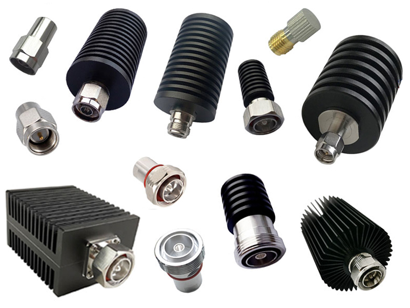
1. By Connector Type and Form Factor
This is the most visible form of classification, determining how the load integrates into a system.
Coaxial Dummy Loads: These are among the most common types, featuring standard RF connectors like N-type, SMA, TNC, and BNC . They are used for terminating coaxial transmission lines and are essential in radio frequency applications. For instance, high-power coaxial loads are governed by military standards like MIL-DTL-39030 , ensuring their reliability in demanding environments like aerospace and defense.
Surface Mount (SMT) Dummy Loads: These are chip-based components soldered directly onto printed circuit boards (PCBs). They are ideal for space-constrained applications within modules like power amplifiers and splitters .
Flange-Mount / High-Power Terminators: Designed for extreme power dissipation, these loads are thermally bonded to a heatsink or chassis. They lack an external connector and are built to handle power levels that can reach 250 watts or more .
2. By Power Handling Capability
The power rating is a primary driver in the design and selection of a dummy load.
Low-Power ( < 1W to a few Watts): Used for signal-level testing, benchtop experiments, and in consumer electronics.
Medium-Power (Up to 100W): Common in amateur radio, commercial radio systems, and laboratory test equipment.
High-Power (100W and above): These are heavy-duty units, often incorporating advanced cooling systems. Examples include loads used in broadcast transmitters and radar systems, with some commercial models capable of handling 10,000 watts . High-power designs for accelerator systems have been tested at pulse powers exceeding 50 MW .
3. By Impedance and Frequency Characteristics
The electrical behavior of a dummy load is defined by its impedance and frequency range.
Impedance: The vast majority of RF systems are designed for a standard characteristic impedance. The most common values are:
50-ohm: The standard for most communication systems and test equipment .
75-ohm: Standard in video broadcasting and cable TV systems .
Frequency Range: Dummy loads are designed to operate over specific frequency bands.
DC to Low Frequency: Simple resistive loads can work from DC up to several hundred MHz.
RF/Microwave: These are engineered for high-frequency performance, covering specific bands like S-band (e.g., around 2.856 GHz) or broader ranges like DC to 6 GHz .
Broadband: Some loads are designed for very wide frequency coverage. For example, the 8930 series of RF loads operates from DC to 400 MHz with a low VSWR, extending up to 1 GHz .
4. By Cooling Method
As power levels increase, dissipating heat becomes the central challenge.
Air-Cooled (Natural Convection): Low to medium-power loads use fins or a metal casing to dissipate heat into the surrounding air.
Air-Cooled (Forced Air): Medium to high-power loads integrate cooling fans to blow air over a heatsink, significantly increasing their power dissipation capacity .
Liquid-Cooled: For the highest power applications, such as in broadcast transmitters or industrial heating, water or other coolants are circulated through the load to carry away immense amounts of heat efficiently .
When selecting a dummy load, it's not just about the connector and power rating. Several performance parameters are critical to ensuring accurate and reliable operation.
Voltage Standing Wave Ratio (VSWR): This is arguably the most important metric for an RF dummy load. It measures the quality of the impedance match. A perfect match would have a VSWR of 1.0:1, meaning all power is absorbed with zero reflection. High-quality dummy loads maintain a very low VSWR across their specified frequency range. For example, precision S-band dummy loads have been demonstrated with a VSWR of less than 1.05 , while commercial broadband loads may specify 1.2:1 or better .
Average and Peak Power Handling: This specifies the maximum continuous (average) and short-duration (peak) power the load can safely handle without damage. Exceeding these ratings can lead to catastrophic failure. It's crucial to select a load with a power rating that has a sufficient safety margin for your application.
Cooling Method and Thermal Management: The cooling technique directly determines the sustainable power level. Designers must consider the power derating curve, which shows the reduced power a load can handle at higher ambient temperatures .
Frequency Range and Impedance: Always ensure the dummy load is designed for the frequencies you intend to use and matches your system's impedance (typically 50Ω or 75Ω). Performance, especially VSWR, is guaranteed only within the specified frequency range.
Connector Type and Durability: The connector must not only be the correct type (N, SMA, etc.) but also of high quality to maintain a consistent impedance and withstand repeated connections. The overall construction should be rugged enough for its operating environment, with some rated for temperatures from -40°C to +45°C and high humidity .
Tags :