


-
We’re On Call 24/7 : +8613538296050
-
E-mail : anna@rohoconnector.com
We’re On Call 24/7 : +8613538296050
E-mail : anna@rohoconnector.com
In the complex world of radio frequency (RF) design, signal integrity is paramount. Among the components that silently ensure this integrity, N-Type terminators stand out for their robustness and reliability. These passive devices play a crucial role in absorbing unwanted RF energy, preventing signal reflections that can distort measurements, damage sensitive equipment, and degrade system performance.
This blog explores the classification and key performance characteristics of N-Type terminators, providing a comprehensive guide for engineers and technicians working with RF systems.
An N-Type terminator is a coaxial load designed to absorb and dissipate RF power while presenting a specific impedance match to the transmission line. The "N-Type" refers to its threaded, weather-resistant connector interface, invented in the 1940s and known for its durability and excellent performance up to 11 GHz, with precision versions operating reliably up to 18 GHz.
Their primary function is to provide a perfectly matched termination for unused ports in RF systems, such as:
The unused port of a power splitter or combiner
The isolation port of a circulator or isolator
Test equipment ports during calibration
Transmitter outputs during testing without radiating a signal
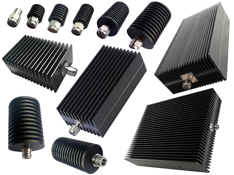
N-Type terminators can be classified based on several key criteria:
This is the most fundamental classification, directly impacting the terminator's size, construction, and cooling method.
Low-Power (1-5 Watts): These are typically compact, portable units with a simple plastic or metal body. They are ideal for general bench testing, laboratory work, and low-power communication systems. Their design relies on natural convection (air cooling) for heat dissipation.
Medium-Power (5-50 Watts): These terminators feature more substantial metal housings, often with cooling fins to increase the surface area for better heat dissipation. They are common in commercial radio, cellular base stations, and medium-power amplifier testing.
High-Power (50-500+ Watts): Built for the most demanding applications, high-power terminators are heavy-duty units with extensive finned heatsinks. In some cases, they may even be designed for forced air or liquid cooling. These are used in broadcast transmitters, high-power radar systems, and industrial RF heating equipment.
The impedance must match the system's characteristic impedance to function correctly.
50-Ohm: This is the standard and most common impedance for the vast majority of RF communication, test, and measurement systems worldwide.
75-Ohm: Less common for N-Type, but available for specific applications, primarily in video broadcasting and some cable television infrastructure.
Standard Connectors: Available in standard male (plug) or female (jack) configurations to match the port requiring termination.
In-Series Terminators (Bullet Style): These unique devices have a female connector on one end and a male on the other. They are inserted directly into a coaxial line to terminate a circuit at that point, rather than at a panel port.
Standard: Suitable for indoor and benign environments.
Weatherproof / IP-Rated: Many N-Type terminators are designed with seals to meet IP67 or similar standards, making them suitable for outdoor use on towers, masts, or in other harsh environments where moisture and dust are concerns.
When selecting an N-Type terminator, several performance parameters are critical to ensure system reliability and accuracy.
This is the single most important specification for a terminator. It measures the quality of the impedance match. A perfect match would have a VSWR of 1.00:1, meaning all power is absorbed with zero reflection.
Standard Quality: VSWR < 1.25:1 across the frequency range.
High Precision: VSWR < 1.10:1 across the frequency range. This is essential for metrology-grade calibration and precision test setups.
A lower VSWR ensures minimal signal reflection, which translates to more accurate measurements and better system performance.
While the N-Type connector is generally reliable up to 11 GHz, the internal design of the terminator dictates its actual operational bandwidth.
DC to 3 GHz: Common for general-purpose terminators.
DC to 6 GHz: Covers cellular and Wi-Fi bands.
DC to 11/18 GHz: Requires a more advanced internal design to maintain a low VSWR at higher frequencies. Always ensure the terminator's frequency specification covers your operating band.
Average Power (in Watts): The maximum continuous power the terminator can dissipate without overheating. Exceeding this rating will cause thermal damage.
Peak Power (in kW or Watts): The maximum short-duration pulse power the terminator can handle. This is particularly important for radar and pulsed systems.
It is good engineering practice to select a terminator with a power rating that has a 20-30% safety margin above your expected maximum operating power.
The terminator's performance should remain stable under varying temperatures.
Operating Temperature Range: High-quality terminators are rated for a wide range, typically from -55°C to +125°C or higher, ensuring functionality in extreme environments.
Derating Curve: The average power rating decreases as the ambient temperature increases. The datasheet will provide a derating curve showing the usable power at elevated temperatures.
Body Material: Typically brass or stainless steel with a nickel or passivated finish for corrosion resistance.
Connector Interface: The center contact and coupling mechanism should be plated with high-quality gold over nickel for low resistance, excellent corrosion resistance, and long mating cycle life.