

-
We’re On Call 24/7 : +8613538296050
-
E-mail : anna@rohoconnector.com
We’re On Call 24/7 : +8613538296050
E-mail : anna@rohoconnector.com
In the diverse world of RF coaxial connectors, the N-Type connector stands as a true workhorse. Developed in the 1940s, it has earned a reputation for ruggedness, reliability, and excellent performance up to 11 GHz (with precision versions reaching 18 GHz). However, no connector exists in isolation. Engineers frequently encounter situations where they must choose between N-Type and similar interfaces, or adapt between them. Understanding the similarities and differences between N-Type and its analogues is essential for making informed design decisions.
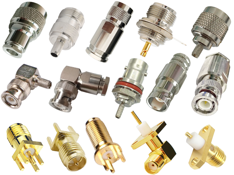
This blog explores how N-Type connectors compare to several similar and often-confused connector families: SMA, BNC, TNC, 7/16 DIN, and UHF (PL-259/SO-239). We examine their shared characteristics, key distinctions, and application-specific trade-offs.
N-Type Connector Overview
Before comparing, let us establish the N-Type's key attributes:
Frequency Range: DC to 11 GHz (standard), DC to 18 GHz (precision)
Impedance: 50 Ω (primary), 75 Ω (available for CATV/video)
Coupling: Threaded (3/8-32 UNF)
Gender: Male (plug) has a protruding center pin; female (jack) has a recessed socket
Typical Power: 50–200 W (depending on frequency and design)
Durability: 500 mating cycles (typical)
Size: Medium (outer diameter ~14–16 mm)
Environmental: Often IP67-rated for outdoor use
Common Applications: Telecommunications, test equipment, broadcast, radar
N-Type vs. SMA Connectors
SMA (SubMiniature version A) connectors are the most common high-frequency alternative to N-Type. While they serve similar functions, their physical size and performance capabilities differ dramatically.
Similarities:
Both are 50 Ω impedance (primarily)
Both use threaded coupling
Both are available in precision grades
Both are widely used in test and measurement
Both offer excellent VSWR performance at their respective frequency limits
Differences:
| Feature | N-Type | SMA |
| Frequency Range | DC – 11 GHz (standard), 18 GHz (precision) | DC – 18 GHz (standard), 26.5 GHz (precision) |
| Size | Large (~16 mm OD) | Small (~5 mm OD) |
| Power Handling | High (50–200 W) | Low (1–50 W) |
| Coupling Torque | ~1.0–1.5 Nm | ~0.7–0.9 Nm |
| Mating Cycles | 500 | 500 |
| Weatherproofing | Excellent (IP67 possible) | Poor (not typically sealed) |
| Cost | Moderate to high | Lower for standard; high for precision |
| Typical Applications | Telecom, broadcast, high power | Test, microwave, compact systems |
Key Trade-Offs:
N-Type is physically larger, which is a disadvantage in dense packaging but an advantage for handling and power dissipation.
SMA is the clear choice for frequencies above 11 GHz where N-Type performance degrades.
For high-power applications (>50 W) at frequencies below 11 GHz, N-Type is superior due to its larger contact area and better heat dissipation.
SMA is generally less expensive and more common in laboratory environments.
When to choose N-Type over SMA: When power handling is critical (transmitter outputs, high-power amplifiers) or when outdoor weatherproofing is required.
When to choose SMA over N-Type: When operating above 11 GHz, when space is at a premium (high-density panels), or when cost is a primary concern for low-power applications.
N-Type vs. BNC Connectors
BNC (Bayonet Neill–Concelman) connectors are ubiquitous in laboratory and video applications. They share a common heritage with N-Type (both named after Paul Neill and Carl Concelman) but differ fundamentally in coupling mechanism and performance.
Similarities:
Both available in 50 Ω and 75 Ω versions
Both are widely used in test and measurement
Both have a similar gender definition (male with center pin)
Both have a comparable size class (BNC is slightly smaller)
Differences:
| Feature | N-Type | BNC |
| Frequency Range | DC – 11 GHz (18 GHz precision) | DC – 4 GHz (6 GHz precision) |
| Coupling | Threaded (secure) | Bayonet (quick connect) |
| Vibration Resistance | Excellent | Poor (can loosen under vibration) |
| Power Handling | High (50–200 W) | Low (1–5 W) |
| Weatherproofing | Excellent (IP67) | Poor (not typically sealed) |
| Mating/Unmating Speed | Slow (threaded) | Fast (bayonet, quarter-turn) |
| Cost | Moderate to high | Low |
| Typical Applications | Telecom, broadcast, high power | Lab equipment, video, low-frequency RF |
Key Trade-Offs:
BNC's bayonet coupling enables quick connection/disconnection, which is essential in laboratory environments where cables are frequently changed.
N-Type's threaded coupling provides superior mechanical integrity and vibration resistance, making it suitable for outdoor and field deployments.
BNC's performance drops above 4 GHz, while N-Type remains excellent to 11 GHz.
BNC is less expensive and more common for general-purpose lab use.
When to choose N-Type over BNC: When operating above 4 GHz, when vibration resistance is required, or when outdoor weatherproofing is needed.
When to choose BNC over N-Type: When quick connect/disconnect is prioritized (lab environments, test benches), when operating below 4 GHz, or when cost is a primary constraint.
N-Type vs. TNC Connectors
TNC (Threaded Neill–Concelman) connectors are essentially threaded versions of BNC. They share the same physical dimensions as BNC but add a threaded coupling nut for improved mechanical security.
Similarities:
Both N-Type and TNC use threaded coupling
Both are 50 Ω (primarily)
Both offer excellent vibration resistance
Both are available in ruggedized versions
Both are named after the same inventors (Neill and Concelman)
Differences:
| Feature | N-Type | TNC |
| Frequency Range | DC – 11 GHz (18 GHz precision) | DC – 11 GHz (18 GHz precision) |
| Size | Large (~16 mm OD) | Small (~8 mm OD) |
| Power Handling | High (50–200 W) | Low to medium (5–50 W) |
| Coupling Torque | ~1.0–1.5 Nm | ~0.5–0.7 Nm |
| Mating Cycles | 500 | 500 |
| Weatherproofing | Excellent (IP67) | Good (can be sealed) |
| Typical Applications | Telecom, broadcast, high power | Military, aerospace, vibration-prone systems |
Key Trade-Offs:
TNC offers the same frequency range as N-Type (to 11 GHz, 18 GHz precision) in a much smaller package.
N-Type handles significantly more power due to its larger contact area and thermal mass.
TNC's smaller size makes it suitable for high-density applications where N-Type would be too large.
Both offer excellent vibration resistance due to threaded coupling.
When to choose N-Type over TNC: When power handling above 50 W is required.
When to choose TNC over N-Type: When space is limited but vibration resistance and moderate power handling are still required, especially in military and aerospace applications.
N-Type vs. 7/16 DIN Connectors
7/16 DIN connectors are large, high-power connectors used extensively in cellular infrastructure and broadcast applications. They represent a step up in size and power capability from N-Type.
Similarities:
Both are 50 Ω impedance
Both use threaded coupling
Both are rugged and weatherproof
Both are available in low-PIM versions
Both are used in outdoor telecom infrastructure
Differences:
| Feature | N-Type | 7/16 DIN |
| Frequency Range | DC – 11 GHz (18 GHz precision) | DC – 7.5 GHz |
| Size | Medium (~16 mm OD) | Large (~21 mm OD) |
| Power Handling | Medium (50–200 W) | Very high (200–600+ W) |
| Coupling Torque | ~1.0–1.5 Nm | ~3.0–3.5 Nm |
| Mating Cycles | 500 | 500 |
| PIM Performance | Good (≤ –150 dBc) | Excellent (≤ –165 dBc) |
| Weatherproofing | Excellent (IP67) | Excellent (IP67/IP68) |
| Cost | Moderate | High |
| Typical Applications | General RF, test, moderate power | Cellular macro cells, broadcast, very high power |
Key Trade-Offs:
7/16 DIN connectors handle significantly higher power (200–600 W) than N-Type (50–200 W), making them essential for high-power transmitters.
7/16 DIN connectors offer inherently lower PIM due to their robust contact pressure and large contact surfaces, critical for multi-carrier cellular systems.
N-Type supports higher frequencies (11 GHz vs. 7.5 GHz), making it more suitable for microwave applications.
7/16 DIN connectors are physically much larger and heavier, requiring more panel space.
7/16 DIN connectors are significantly more expensive.
When to choose N-Type over 7/16 DIN: When operating above 7.5 GHz, when panel space is limited, or when the power requirement is below 200 W and cost is a factor.
When to choose 7/16 DIN over N-Type: When power handling above 200 W is required, when ultra-low PIM is critical (multi-carrier cellular), or when compatibility with existing 7/16 DIN infrastructure is needed.
N-Type vs. UHF Connectors (PL-259/SO-239)
UHF connectors, commonly known by their military designations PL-259 (male plug) and SO-239 (female jack), are the oldest connector type still in widespread use. Despite their name, they are not suitable for UHF frequencies.
Similarities:
Both are threaded connectors
Both are 50 Ω impedance (approximately)
Both are rugged and can handle moderate power
Both are used in amateur radio and communications
Differences:
| Feature | N-Type | UHF (PL-259/SO-239) |
| Frequency Range | DC – 11 GHz (18 GHz precision) | DC – 300 MHz (usable to 1 GHz) |
| Impedance | Controlled 50 Ω | Not constant (varies with frequency) |
| Size | Medium (~16 mm OD) | Large (~20 mm OD) |
| Power Handling | 50–200 W | 50–100 W |
| Coupling | Threaded (3/8-32 UNF) | Threaded (5/8-24 UNF) |
| VSWR at 1 GHz | ≤ 1.15:1 | Poor (~1.5:1 to 2.0:1) |
| Weatherproofing | Excellent (IP67) | Moderate (rubber gasket) |
| Cost | Moderate to high | Low |
| Typical Applications | Telecom, test, microwave | Amateur radio, legacy systems, low-frequency |
Key Trade-Offs:
UHF connectors have a non-constant impedance, making them unsuitable for precision RF applications above 300 MHz.
N-Type provides controlled impedance and excellent VSWR up to 11 GHz.
UHF connectors are significantly less expensive and easier to field-terminate (solder or crimp).
N-Type connectors are more weatherproof and durable for outdoor use.
UHF connectors are increasingly obsolete for new designs but persist in amateur radio and legacy systems.
Summary Comparison Table
When to choose N-Type over UHF: For any application above 300 MHz, when controlled impedance is required, or when precision measurements are needed.
When to choose UHF over N-Type: For low-frequency (<300 MHz) amateur radio applications, when cost is the primary constraint, or when maintaining compatibility with legacy equipment.
| Feature | N-Type | SMA | BNC | TNC | 7/16 DIN | UHF |
| Max Frequency | 11/18 GHz | 18/26.5 GHz | 4/6 GHz | 11/18 GHz | 7.5 GHz | 0.3/1 GHz |
| Impedance (Ω) | 50 (75) | 50 | 50 (75) | 50 | 50 | Nominal 50 |
| Coupling | Threaded | Threaded | Bayonet | Threaded | Threaded | Threaded |
| Power Handling | High | Low | Low | Medium | Very High | Medium |
| Vibration Resistant | Excellent | Good | Poor | Excellent | Excellent | Moderate |
| Weatherproof | Excellent | Poor | Poor | Good | Excellent | Moderate |
| Size | Medium | Small | Small | Small | Large | Large |
| Primary Use | Telecom, test | Test, microwave | Lab, video | Military, aero | Cellular, broadcast | Amateur radio |
Intermating and Adapters
One critical point: N-Type connectors are not mechanically compatible with any of the above connector types. They cannot be mated directly with SMA, BNC, TNC, 7/16 DIN, or UHF connectors. Adapters are required to convert between any of these interfaces.
| Adapter Type | Purpose |
| N-Type to SMA | Connect high-power N-Type equipment to standard SMA test leads |
| N-Type to BNC | Connect outdoor N-Type cables to lab BNC instruments |
| N-Type to TNC | Convert between similar-frequency, threaded connectors with different sizes |
| N-Type to 7/16 DIN | Interconnect legacy/moderate-power systems with high-power cellular infrastructure |
| N-Type to UHF | Connect modern N-Type equipment to legacy UHF gear |
When using adapters, be aware that each adapter introduces additional insertion loss (typically 0.05–0.15 dB), degrades VSWR slightly, and reduces the overall frequency range to the lower of the two connector types.
| Application | Recommended Connector | Alternative | Reason |
| High-frequency lab test (>11 GHz) | SMA | 3.5mm, 2.92mm | SMA is standard for microwave |
| General lab test (<4 GHz) | BNC | N-Type | BNC is quick-connect and inexpensive |
| Vibration-prone systems | TNC | N-Type | TNC is threaded and compact |
| Outdoor telecom (<11 GHz, <200 W) | N-Type | 4.3-10 | N-Type is proven, weatherproof |
| High-power telecom (>200 W, <7.5 GHz) | 7/16 DIN | N-Type (if <200 W) | 7/16 DIN handles more power |
| Amateur radio (<300 MHz) | UHF | N-Type (if budget allows) | UHF is low-cost, field-terminable |
| Broadcast transmitter | 7/16 DIN | N-Type (for lower power) | 7/16 DIN handles high power and low PIM |
| Compact high-density | SMA | TNC | SMA is smallest among high-performance |
The N-Type connector occupies a unique position in the RF connector ecosystem. It is larger and more robust than SMA and TNC, handles more power than BNC, operates to higher frequencies than 7/16 DIN, and offers controlled impedance and superior performance compared to UHF. Its threaded coupling provides excellent vibration resistance, and its weatherproof variants are trusted for outdoor infrastructure deployments worldwide.
When choosing between N-Type and its analogues, the decision hinges on four primary factors:
Frequency: For frequencies above 11 GHz, move to SMA, 2.92mm, or 2.4mm. For frequencies below 4 GHz, BNC may suffice.
Power: For power handling above 200 W, 7/16 DIN is preferred. Below 50 W, SMA or TNC may be adequate.
Mechanical Environment: For vibration-prone systems, TNC or 7/16 DIN are ideal. For quick-connect lab use, BNC is unmatched.
Application Context: Compatibility with existing infrastructure, cost, and environmental sealing requirements all influence the decision.
Understanding the similarities and differences between N-Type and its analogues enables engineers to select the optimal connector for each application, ensuring signal integrity, reliability, and cost-effectiveness across the RF system.