


-
We’re On Call 24/7 : +8613538296050
-
E-mail : anna@rohoconnector.com
We’re On Call 24/7 : +8613538296050
E-mail : anna@rohoconnector.com
In the vast ecosystem of radio frequency (RF) systems, no component is more fundamental—or more varied—than the antenna. While amplifiers boost signals, filters select frequencies, and cables guide them, it is the antenna that performs the essential transformation: converting guided electromagnetic waves traveling along a transmission line into free-space waves that radiate outward, and vice versa. Antennas are the interface between the electronic world of circuits and the physical world of propagating waves.
This blog explores the classification and key performance characteristics of RF antennas, providing engineers, system designers, and enthusiasts with a comprehensive guide to understanding and selecting antennas for their applications.
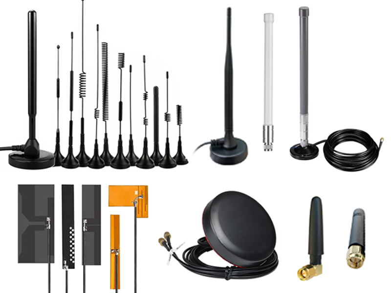
An RF antenna is a transducer that converts electrical currents into electromagnetic waves (transmit mode) or captures electromagnetic waves and converts them into electrical currents (receive mode). The term "antenna" encompasses an extraordinary diversity of designs, from the simple quarter-wave monopole on a handheld radio to the massive parabolic reflectors used in deep-space communication.
Antennas are characterized by their ability to:
Radiate or receive energy efficiently in specific directions
Match impedance to the transmission line (typically 50 Ω or 75 Ω)
Operate over a defined frequency band
Maintain polarization purity
Survive mechanical and environmental stresses
RF antennas can be classified according to several criteria: physical structure, radiation pattern, frequency range, polarization, and application.
This is the most intuitive classification, based on the antenna's geometric design.
Wire Antennas
These are among the simplest and oldest antenna forms, consisting of conductive elements in various configurations.
| Type | Description | Typical Applications |
| Dipole | Two conductive elements, typically half-wavelength long | FM radio, TV, base station, amateur radio |
| Monopole | Single element above a ground plane | Mobile communications, handheld devices |
| Loop | Closed-loop conductor (small or large) | Direction-finding, RFID, AM radio |
| Helical | Wire wound in a helix | Satellite communications, GPS, handheld radios |
| Yagi-Uda | Driven element with parasitic elements (directors and reflectors) | TV reception, point-to-point links, amateur radio |
| Log-Periodic | Multiple elements of increasing length | Broadband communications, TV, EMC testing |
Aperture Antennas
These antennas radiate through an opening or aperture.
| Type | Description | Typical Applications |
| Horn | Flared waveguide section | Microwave links, radar, test and measurement |
| Parabolic Reflector | Parabolic dish with a feed at the focus | Satellite communication, radio telescopes, radar |
| Slot | Slot cut in a conductive surface | Aircraft antennas, conformal arrays |
| Cassegrain | Dual-reflector (parabolic main + hyperbolic sub-reflector) | Deep-space communication, high-gain microwave |
Microstrip (Patch) Antennas
Planar antennas fabricated on printed circuit boards.
| Type | Description | Typical Applications |
| Rectangular Patch | Simple rectangular conductive patch over a ground plane | Mobile devices, GPS, WLAN, automotive |
| Circular Patch | Circular radiating element | Satellite navigation, wireless sensors |
| Planar Inverted-F (PIFA) | Compact, low-profile patch | Mobile phones, Bluetooth, IoT |
| Microstrip Array | Multiple patches arranged in an array | Phased arrays, radar, 5G base stations |
Array Antennas
Multiple radiating elements arranged to achieve specific radiation patterns.
| Type | Description | Typical Applications |
| Phased Array | Phase-controlled elements for electronic beam steering | Radar, 5G massive MIMO, satellite |
| Corporate Feed Array | Power-dividing network feeding multiple elements | Communication satellites, ground stations |
| Series-Fed Array | Elements fed in series | Low-cost radar, automotive sensors |
| Slotted Waveguide | Slots cut into waveguide walls | Radar systems, navigation |
Traveling-Wave Antennas
Where the wave travels along the structure and radiates continuously.
| Type | Description | Typical Applications |
| Leaky-Wave | Wave leaks progressively along the structure | Automotive radar, sensing |
| Surface-Wave | Guided surface wave radiates at discontinuities | Specialized military and industrial |
The radiation pattern describes how an antenna distributes energy in space.
| Pattern Type | Description | Typical Gain | Applications |
| Omnidirectional | Radiates equally in all directions in one plane (e.g., vertical dipole) | 1 – 4 dBi | Broadcast, mobile devices, Wi-Fi |
| Sectoral | Covers a specific angular sector (e.g., 60° or 90°) | 8 – 16 dBi | Cellular base stations, Wi-Fi access points |
| Directional | Radiates primarily in one direction (e.g., Yagi, horn) | 6 – 20 dBi | Point-to-point links, TV reception |
| Highly Directional | Narrow beam (e.g., parabolic reflector) | 20 – 60+ dBi | Satellite communication, radio telescopes |
| Isotropic (Theoretical) | Radiates equally in all directions (3D) | 0 dBi | Reference only |
Antennas are designed for specific frequency bands, with dimensions scaling inversely with frequency.
| Band | Frequency Range | Typical Antenna Types |
| VLF / LF | 3 – 300 kHz | Large loop, monopole (very long) |
| MF / HF | 300 kHz – 30 MHz | Dipole, monopole, vertical, Yagi |
| VHF | 30 – 300 MHz | Dipole, Yagi, whip, folded dipole |
| UHF | 300 MHz – 3 GHz | Patch, monopole, Yagi, helical, slot |
| SHF (Microwave) | 3 – 30 GHz | Horn, parabolic, patch array, slot array |
| EHF (Millimeter-wave) | 30 – 300 GHz | Microstrip arrays, lens, leaky-wave, horn |
| THz | 300 GHz – 3 THz | Rectenna, printed arrays, photoconductive |
Polarization describes the orientation of the electric field vector of the radiated wave.
| Polarization Type | Description | Applications |
| Linear (Vertical) | Electric field vertical | FM radio, broadcast, mobile |
| Linear (Horizontal) | Electric field horizontal | TV broadcast, point-to-point |
| Linear (Slant) | Electric field at 45° | Certain satellite, DBS (Direct Broadcast Satellite) |
| Circular (Right-Hand / Left-Hand) | Electric field rotates | Satellite communication, GPS, radar |
| Dual / Cross-Polarized | Two orthogonal polarizations | 5G MIMO, radar polarimetry |
| Elliptical | General case between linear and circular | Specialized applications |
Application
| Application | Typical Antenna Types | Key Requirements |
| Cellular Base Stations | Sectoral panel, dipole array, massive MIMO arrays | High gain, low VSWR, weatherproof, low PIM |
| Mobile Devices | PIFA, monopole, patch | Compact, omnidirectional, low SAR |
| Wi-Fi / Bluetooth | Patch, dipole, omni-directional, sectoral | Omnidirectional or sectoral, low cost |
| Satellite Communication | Parabolic reflector, helical, horn, patch array | High gain, circular polarization, weatherproof |
| GPS / GNSS | Patch, helical, ceramic | Circular polarization, low-noise, stable phase center |
| Radar | Parabolic, phased array, slotted waveguide, horn | High gain, narrow beam, pulse power |
| TV / Broadcast | Dipole, Yagi, log-periodic, omnidirectional | Broadband, low VSWR, high gain |
| Test & Measurement | Horn, dipole, log-periodic, standard-gain | Calibrated gain, stable phase center, precision |
| Automotive | Patch, monopole, Yagi | Compact, vibration-tolerant, weatherproof |
| IoT / Sensors | Chip antenna, PCB trace, small patch | Ultra-compact, low cost, integrated |
The performance of an RF antenna is defined by a set of critical electrical and mechanical parameters. The table below summarizes typical specifications for common antenna types.
| Parameter | Omnidirectional (Dipole) | Directional (Yagi) | Highly Directional (Parabolic) | Patch (Microstrip) |
| Gain (Typical) | 2 – 4 dBi | 6 – 15 dBi | 20 – 50 dBi | 3 – 8 dBi |
| Beamwidth (Typical) | 360° (azimuth) | 30° – 80° | 1° – 10° | 60° – 100° |
| VSWR (Typical) | 1.5:1 – 2.0:1 | 1.5:1 – 1.8:1 | 1.2:1 – 1.5:1 | 1.5:1 – 2.0:1 |
| Bandwidth | Narrow to moderate | Moderate | Narrow to moderate | Narrow (typ. 5–10%) |
| Polarization | Linear (vertical or horizontal) | Linear | Linear or circular | Linear (or circular with design) |
| Front-to-Back Ratio | N/A | 10 – 20 dB | 20 – 40 dB | 10 – 15 dB |
| Typical Power Handling | 10 – 100 W | 10 – 500 W | 100 W – kW+ | 1 – 50 W |
Detailed Parameter Explanations
1. Gain
Gain is the most commonly cited antenna specification. It measures the antenna's ability to concentrate radiated power in a specific direction compared to an isotropic radiator (which radiates equally in all directions).
Isotropic Gain: 0 dBi (theoretical reference)
Dipole Gain: 2.15 dBd (or 2.15 dBi)
High-Gain Directional: 20 – 50 dBi (parabolic reflectors)
Gain is directional: an antenna with high gain has a narrow beam and vice versa. For communication links, higher gain means stronger signal and longer range, but it requires precise alignment.
2. Radiation Pattern and Beamwidth
The radiation pattern describes the spatial distribution of radiated energy. The half-power beamwidth (HPBW) is the angular width of the main lobe where the power is at least half (-3 dB) of the peak. A narrower beamwidth indicates higher gain but less coverage area.
3. Return Loss and VSWR
VSWR (Voltage Standing Wave Ratio) measures how well the antenna is matched to the transmission line impedance (typically 50 Ω). A perfect match is 1.00:1. For most antennas:
Good: VSWR ≤ 1.5:1
Acceptable: VSWR ≤ 2.0:1
Poor: VSWR > 2.0:1 (significant reflections)
Poor VSWR reduces radiated power and can damage the transmitter.
4. Bandwidth
Bandwidth is the frequency range over which the antenna maintains its specified performance (gain, VSWR, pattern). It is usually expressed as:
Absolute Bandwidth: f₂ – f₁ (in Hz)
Fractional Bandwidth: (f₂ – f₁) / f₀ × 100%
Relative Bandwidth: Ratio f₂ / f₁
Narrowband antennas: 1–5% bandwidth (microstrip patch).
Broadband antennas: 10–50% bandwidth (log-periodic, horn, helical).
Ultrawideband (UWB): > 50% bandwidth.
5. Polarization
Polarization must match between transmitting and receiving antennas. A cross-polarized situation (vertical to horizontal) results in 20–30 dB loss. Circular polarization is advantageous for satellite communications where orientation varies.
6. Efficiency and Radiation Efficiency
Efficiency accounts for losses within the antenna:
Conduction Loss: Resistive heating in conductors
Dielectric Loss: Loss in insulating materials
Radiation Efficiency: Ratio of radiated power to input power (≤ 100%)
7. Front-to-Back Ratio (F/B)
For directional antennas, the front-to-back ratio measures the ratio of the forward radiation to backward radiation. A high F/B ratio indicates minimal radiation in the reverse direction, reducing interference.
8. Input Impedance
The antenna's input impedance must match the transmission line. For most RF systems, this is 50 Ω (or 75 Ω for CATV). A reactive impedance (with significant inductance or capacitance) requires a matching network to achieve resonance.
9. Power Handling
The maximum input power the antenna can handle without damage, limited by heating in conductors, dielectric breakdown, and connector limitations.
10. Mechanical and Environmental Specifications
Wind Loading: Important for outdoor antennas
Weight / Size: Critical for portable, aircraft, and space applications
Ingress Protection (IP Rating): For outdoor use
Temperature Range: Important for extreme environments
UV and Corrosion Resistance: For tower-mounted antennas
Outgassing: For space applications
Antenna Performance in Practice
| Application | Typical Antenna | Gain | Beamwidth | VSWR | Polarization | Remarks |
| FM Radio Broadcast | Dipole (folded) | 2 – 4 dBi | 360° | 1.5:1 | Vertical | Omnidirectional |
| Cellular Base Station | Panel sectoral (3-sect.) | 15 – 18 dBi | 60°–90° | 1.3:1 | Dual slant (±45°) | Low PIM, weatherproof |
| Point-to-Point Link | Parabolic dish | 24 – 40 dBi | 1°–5° | 1.2:1 | Linear or circular | Highly directional, weatherproof |
| GPS Receiver | Patch / helical | 3 – 5 dBi | hemispherical | 1.5:1 | RHCP | Low noise, stable phase center |
| Wi-Fi Access Point | Omni / patch array | 3 – 10 dBi | 360° / sectoral | 1.5:1 | Linear | Compact, indoor/outdoor |
| Automotive Radar | Patch array / leaky-wave | 10 – 20 dBi | narrow (10°–20°) | 1.5:1 | Linear | Compact, 77 GHz |
| Satellite Dish (home) | Parabolic (offset) | 30 – 40 dBi | 1°–2° | 1.2:1 | Linear | Circular (weatherproof) |
| Horn (standard gain) | Rectangular horn | 10 – 20 dBi | 10°–30° | 1.2:1 | Linear | Precision, calibration-grade |
Selection Guidelines for Engineers
| Factor | Considerations |
| Frequency Range | Ensure the antenna covers your operating band and any harmonics. |
| Gain | Higher gain means longer range but narrower beam; choose according to link budget. |
| Radiation Pattern | Omnidirectional for coverage; directional for point-to-point. |
| Polarization | Match transmitter and receiver; consider circular for satellite/space. |
| VSWR / Return Loss | Specify ≤ 1.5:1 for critical applications; ≤ 2.0:1 acceptable for general. |
| Power Handling | Include a safety margin; derate for high ambient temperatures. |
| Size / Weight | Critical for portable, aircraft, and space applications. |
| Environmental | Consider wind, rain, temperature, UV, salt spray for outdoor use. |
| Connector Type | Match to system interface (SMA, N-Type, TNC, etc.). |
| Mounting | Antenna mounting must be robust and correctly oriented. |
| Cost | Balance performance with budget; custom antennas are more expensive than off-the-shelf. |
| Regulatory | Ensure compliance with regional regulations (FCC, ETSI, etc.). |
Common Installation and Maintenance Practices
Location: Clear line-of-sight for directional links; proper height for coverage; avoid metal obstructions.
Cable routing: Use high-quality coax with low loss; minimize length; avoid sharp bends.
Grounding: Proper lightning protection and grounding.
Weatherproofing: Seal connectors and junctions to prevent moisture ingress.
PIM and interference: Keep antennas away from metallic structures and other radiating elements.
Inspection: Periodically check for corrosion, mechanical damage, and connector integrity.
Future Trends in Antenna Technology
Massive MIMO and Beamforming: 5G and 6G networks use arrays with dozens or hundreds of elements for dynamic beam steering.
Reconfigurable Antennas: Antennas that can change frequency, pattern, or polarization electronically.
Metamaterials and Reconfigurable Intelligent Surfaces (RIS): Electrically tunable surfaces for beam control and signal enhancement.
Integrated Antennas: On-chip and package-integrated antennas for 5G, mmWave, and IoT devices.
AI-Driven Design: Machine learning for antenna optimization and synthesis.
Sustainable Materials: Environmental and recycling considerations in antenna manufacturing.