


-
We’re On Call 24/7 : +8613538296050
-
E-mail : anna@rohoconnector.com
We’re On Call 24/7 : +8613538296050
E-mail : anna@rohoconnector.com
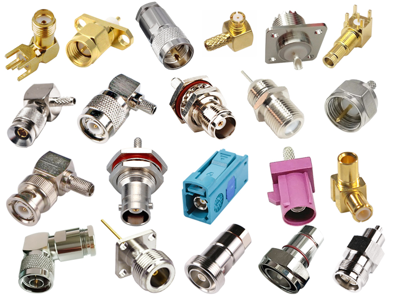
In the intricate world of radio frequency (RF) and microwave engineering, connectors are the unsung heroes that enable seamless signal transmission between components, cables, and systems. Despite their small size, RF connectors play a pivotal role in determining system performance, reliability, and longevity. Selecting the wrong connector can introduce signal loss, reflections, and even catastrophic system failure.
This comprehensive guide explores the classification and key performance characteristics of RF connectors, providing engineers and technicians with the knowledge needed to make informed decisions for their applications.
An RF connector is an electromechanical device designed to join coaxial cables, transmission lines, or components while maintaining the characteristic impedance of the system. Unlike low-frequency connectors, RF connectors are engineered to preserve signal integrity at high frequencies by minimizing reflections, leakage, and loss.
RF connectors are characterized by:
Controlled impedance (typically 50 Ω or 75 Ω)
Specified frequency range up to which performance is guaranteed
Mechanical durability measured in mating cycles
Environmental robustness for various operating conditions
Reliability in maintaining consistent electrical contact
RF connectors can be classified according to several criteria: frequency range, size, coupling mechanism, impedance, and application-specific design.
One of the most fundamental ways to classify RF connectors is by their maximum operating frequency, which is closely related to their physical size. In general, smaller connectors can operate at higher frequencies because they exhibit less parasitics and can maintain a more consistent impedance profile.
Subminiature Connectors (Highest Frequency)
| Connector Family | Frequency Range | Typical Outer Diameter |
| 1.0mm | DC – 110 GHz | 1.0 mm |
| 1.85mm | DC – 67 GHz | 1.85 mm |
| 2.4mm | DC – 50 GHz | 2.4 mm |
| 2.92mm (K) | DC – 40 GHz | 2.92 mm |
| 3.5mm | DC – 34 GHz | 3.5 mm |
These connectors are used in millimeter-wave applications, advanced research, 5G testing, and high-speed digital systems.
Medium-Size Connectors (High Frequency)
| Connector Family | Frequency Range | Common Applications |
| SMA | DC – 18 GHz (up to 26.5 GHz precision) | Telecommunications, test, aerospace |
| TNC | DC – 11 GHz (up to 18 GHz precision) | Military, industrial, vibration-resistant |
| SMB / SMC | DC – 4 GHz (up to 10 GHz) | Snap-on, compact, modular systems |
| MCX / MMCX | DC – 6 GHz (MCX), DC – 6 GHz (MMCX) | Ultra-compact, portable devices |
| BNC | DC – 4 GHz (up to 6 GHz precision) | Lab equipment, video, low-frequency RF |
| F-Type | DC – 3 GHz (up to 6 GHz) | CATV, satellite, consumer broadband |
Large Connectors (Lower Frequency, Higher Power)
| Connector Family | Frequency Range | Typical Applications |
| N-Type | DC – 11 GHz (up to 18 GHz precision) | Telecommunications, test, high power |
| 7/16 DIN | DC – 7.5 GHz | Macro base stations, broadcast, high power |
| 4.3-10 | DC – 6 GHz | Dense cellular infrastructure, low PIM |
| UHF (PL-259/SO-239) | DC – 300 MHz (usable to 1 GHz) | Amateur radio, legacy systems |
| MHV | DC – 300 MHz (up to 500 MHz) | High-voltage, nuclear instrumentation |
| SHV | DC – 300 MHz | Safe high-voltage applications |
RF connectors employ different mechanical coupling methods, each offering distinct advantages in terms of speed, security, and vibration resistance.
| Coupling Type | Examples | Key Characteristics |
| Threaded | SMA, N-Type, TNC, 7/16 DIN, 4.3-10 | Most secure, best vibration resistance, requires proper torque |
| Bayonet | BNC, UHF | Quick connect/disconnect, moderate security, susceptible to vibration |
| Snap-On / Push-On | SMB, SMC, MCX | Very quick, compact, limited mating cycles |
| Slide-On / Push-Pull | MMCX, QMA (Quick-Lock SMA) | Fast, compact, some allow rotation |
| Hermetic / Glass Sealed | Specialized types | Vacuum-tight, aerospace and nuclear applications |
Threaded connectors provide the most reliable electrical connection under vibration. Bayonet connectors offer a good balance of speed and security for laboratory use. Snap-on connectors are ideal for high-density applications where space is at a premium and frequent connections are required.
RF connectors are designed for specific system impedances:
50 Ω: The universal standard for telecommunications, wireless, RF test equipment, and most aerospace/military applications.
75 Ω: Used primarily in video, cable television (CATV), satellite receivers, and some broadcast applications.
95 Ω and 100 Ω connectors exist for specialized balanced lines and differential signaling (rare).
It is critical to match connector impedance to system impedance. Using a 50 Ω connector in a 75 Ω system introduces mismatch loss (approximately 4–5 dB extra loss) and reflections that degrade performance.
Connector materials directly affect electrical performance, durability, and environmental resistance:
Body: Brass (with nickel, silver, or gold plating) for standard applications; stainless steel for high-durability or corrosion-resistant applications; aluminum for lightweight designs.
Center Contact: Beryllium copper or phosphor bronze for spring properties; brass for simple contacts; all are plated with gold (preferred) or silver for low contact resistance.
Dielectric (Insulator): PTFE (Teflon) is the standard for its low loss and stable dielectric constant; air (in precision connectors) offers the lowest loss but requires careful support structures; proprietary materials (e.g., PEI, PEEK) for high-temperature applications.
Coupling Nut: Brass with nickel plating for durability; stainless steel for premium connectors.
| Application | Connector Types | Special Requirements |
| Cellular Infrastructure | 4.3-10, 7/16 DIN, N-Type | Low PIM, high power, outdoor weatherproof |
| Test & Measurement | SMA, 2.92mm, 3.5mm, N-Type | Precision VSWR, repeatability, calibration-grade |
| Military / Aerospace | TNC, N-Type, SMA, SHV | High durability, wide temperature range, MIL-STD compliance |
| Satellite & Space | SMA (hermetic), 2.4mm, 1.85mm | Outgassing limits, wide temperature range, radiation resistance |
| Consumer / Broadcast | F-Type, BNC, RCA | Low cost, ease of installation, 75 Ω |
| Medical & Industrial | MHV, SHV, N-Type | High voltage, sterilization compatibility |
| Automotive | FAKRA, SMA | Vibration tolerance, low cost, compact size |
When selecting an RF connector, engineers must evaluate a comprehensive set of electrical, mechanical, and environmental parameters.
The frequency range is the connector's specified operating bandwidth. Within this range, the connector maintains its electrical performance, particularly VSWR (Voltage Standing Wave Ratio).
VSWR quantifies impedance matching. A VSWR of 1.00:1 is perfect; 1.20:1 is excellent; 1.50:1 is acceptable for many applications.
Return Loss is the logarithmic expression of VSWR. Higher return loss (e.g., 20 dB or more) indicates better impedance matching.
Cutoff frequency is determined by the connector's internal dimensions; above this frequency, the connector may support unwanted propagation modes, causing performance degradation.
Insertion loss is the signal power lost as it passes through the connector. Sources include:
Conductor loss (resistive heating in center and outer conductors)
Dielectric loss (energy absorbed by the insulator)
Reflection loss (power reflected due to impedance mismatch)
Insertion loss is typically specified in decibels per GHz per connector. High-quality precision connectors have loss below 0.1 dB up to their cutoff frequency, while general-purpose connectors may have 0.2–0.3 dB at their maximum frequency. In cable assemblies, loss accumulates across multiple connectors and cable length.
The maximum power a connector can safely transmit is determined by:
Average power: Limited by thermal dissipation; higher power requires larger connectors (e.g., 7/16 DIN for 500 W).
Peak power: Limited by voltage breakdown and arcing; connectors with larger spacing (e.g., 7/16 DIN, MHV) handle higher voltages.
Frequency: Power handling decreases with frequency due to skin-effect losses.
Temperature: Derating applies at elevated ambient temperatures.
| Connector Type | Typical Average Power (CW at 1 GHz) | Peak Power Capability |
| SMA | 1–50 W | 100–500 W |
| N-Type | 50–200 W | 1–5 kW |
| 7/16 DIN | 200–600 W | 5–10 kW |
| UHF | 50–100 W | 1–2 kW |
Center Contact Resistance: Typically 1–3 mΩ; lower is better to minimize heating and signal loss.
Outer Contact Resistance: Typically 0.5–1 mΩ.
Insulation Resistance: > 5,000 MΩ to prevent leakage and arcing; critical in high-voltage applications (e.g., MHV, SHV).
Dielectric Withstanding Voltage: The voltage the connector can withstand before breakdown; e.g., MHV > 5 kV.
PIM is a critical specification for connectors used in multi-carrier cellular systems, especially those handling high transmit power.
PIM occurs when two or more high-power RF signals mix at a nonlinear junction (e.g., poor contact, contamination, or ferromagnetic materials).
PIM performance is expressed in dBc (decibels relative to carrier). A –160 dBc specification means the intermodulation product is 160 dB below the carrier.
Connectors designed for low-PIM use non-ferromagnetic materials (brass, stainless steel), high-quality plating (silver or low-PIM nickel), and careful assembly.
4.3-10 and 7/16 DIN connectors are inherently low-PIM; SMA and N-Type can also achieve low-PIM with special design.
RF connectors are deployed in a wide range of environments, from clean laboratories to harsh outdoor towers.
Operating Temperature: Commercial (-40°C to +85°C), Industrial (-55°C to +125°C), Aerospace (-65°C to +165°C).
Ingress Protection (IP): IP67/IP68 for weatherproof connectors used outdoors; IP40 for indoor use.
Corrosion Resistance: Plating (nickel, silver, gold) prevents oxidation; stainless steel bodies resist corrosion in marine environments.
Outgassing: Critical for space applications; connectors must meet NASA or ESA outgassing limits.
UV Resistance: For outdoor and tower-top connectors.
Mating Cycles: Standard connectors are rated for 500 mating cycles; precision connectors for 1,000+ cycles; SMA for 500–1,000 cycles; BNC for 500 cycles; N-Type for 500 cycles; 7/16 DIN for 500 cycles.
Coupling Torque: Threaded connectors require proper torque (e.g., 7/16 DIN at 3.0–3.5 Nm; N-Type at 1.0–1.5 Nm) for consistent performance and to prevent damage.
Cable Retention: Critical for cable-mounted connectors; must withstand specified pull forces.
Vibration and Shock: TNC (threaded) and 7/16 DIN (large thread) are the most vibration-resistant; BNC is the least.
To select the optimal RF connector for your application, follow this decision framework:
| System Requirement | Recommended Connector Family | Key Specifications |
| Highest frequency > 40 GHz | 1.0mm, 1.85mm, 2.4mm | Precision VSWR, low insertion loss |
| Highest frequency 18–40 GHz | 2.92mm, 3.5mm, precision SMA | VSWR ≤ 1.25:1, metrology-grade |
| General RF up to 18 GHz | SMA, N-Type | VSWR ≤ 1.3:1, 500+ mating cycles |
| High power > 200 W | 7/16 DIN, N-Type | Power rating, low PIM (for cellular) |
| Vibration-resistant outdoor | TNC, 7/16 DIN, N-Type | Threaded coupling, IP67, wide temperature |
| Quick-connect lab use | BNC | Bayonet coupling, 50 Ω or 75 Ω |
| Video / broadcast | BNC (75 Ω), F-Type, RCA | 75 Ω impedance, low loss |
| Cellular / low-PIM | 4.3-10, 7/16 DIN | PIM ≤ –160 dBc, IP67 |
| High voltage > 1 kV | MHV, SHV, N-Type (high-voltage variants) | Dielectric strength, safety |
| Compact / high-density | SMB, SMC, MCX, MMCX | Snap-on coupling, minimal footprint |
| Space / vacuum | SMA (hermetic), N-Type (hermetic) | Outgassing, hermetic seal, wide temperature |
| Cost-sensitive consumer | F-Type, BNC, RCA | Low cost, ease of termination |
Impedance mismatch: Using a 50 Ω connector in a 75 Ω system or vice versa. Always verify impedance.
Incorrect torque: Over-torquing damages threads; under-torquing causes poor contact, high VSWR, and PIM.
Cross-threading: Threaded connectors must be carefully aligned before tightening.
Using the wrong gender: Always check the port and cable connector genders.
Contamination: Dirt, oil, or oxidation on center contacts causes high loss and PIM; clean connectors with appropriate tools.
Mechanical stress: Cables should be supported to prevent stress on connectors, especially in high-vibration environments.
Ignoring derating: Power ratings apply at specified ambient temperatures; derate at elevated temperatures.
RF connectors have gender based on the center contact:
Male (Plug): Has a protruding center pin.
Female (Jack): Has a recessed center socket.
Reverse Polarity (RP): Reverse-polarity connectors have the opposite center contact gender (e.g., RP-SMA male has a female center socket) and are used in Wi-Fi and consumer devices to comply with regulations.
Always confirm gender when ordering adapters or cables.
RF connectors are the critical interface between cables, components, and systems. Their classification by frequency range, size, coupling mechanism, and impedance provides a framework for selection, while key performance characteristics such as VSWR, insertion loss, power handling, PIM, environmental robustness, and mechanical durability define their suitability for each application.
The connector you choose can significantly impact system performance, reliability, and long-term cost. By understanding the families—from the tiny 1.0mm used in millimeter-wave research to the robust 7/16 DIN that anchors cellular towers—and their specifications, engineers can make informed decisions.
The golden rule: always choose a connector that is electrically, mechanically, and environmentally matched to the demands of your system. When in doubt, consult the manufacturer's datasheet, verify the impedance and frequency range, and consider safety and environmental factors. The right connector, properly installed, will provide years of reliable, low-loss performance.