


-
We’re On Call 24/7 : +8613538296050
-
E-mail : anna@rohoconnector.com
We’re On Call 24/7 : +8613538296050
E-mail : anna@rohoconnector.com
As wireless infrastructure continues to densify and evolve toward 5G-Advanced and beyond, the components that form the backbone of these networks must adapt to new demands: higher power, lower passive intermodulation (PIM), greater port density, and smaller form factors. Among the innovations meeting these challenges head-on is the 4.3-10 power splitter. This component leverages the compact, high-performance 4.3-10 connector interface—originally developed to replace bulky 7/16 DIN connectors in space-constrained base stations—to deliver exceptional RF distribution capabilities in a significantly smaller footprint.
This blog post explores the classification and key performance characteristics of 4.3-10 power splitters, providing engineers and system integrators with the essential knowledge to select and deploy these critical components in next-generation networks.
A 4.3-10 power splitter (also known as a power divider) is a passive device that takes a single RF input signal and divides it into two or more output signals, maintaining proper impedance matching (50 Ω, the universal standard for communication systems) across all ports. The 4.3-10 connector interface, standardized under IEC 61169-54, features a threaded coupling mechanism with a 4.3 mm outer conductor diameter (hence the name) and a 10 mm coupling nut. It was designed to offer the electrical and mechanical robustness of the 7/16 DIN interface—including excellent low-PIM performance—while reducing size and weight by approximately 50%, enabling higher port density on equipment panels.
Power splitters with 4.3-10 connectors are widely used in:
Cellular base stations (macro, micro, and small cells)
Distributed antenna systems (DAS)
In-building coverage solutions
Public safety communication networks
Test and measurement setups for 5G infrastructure
4.3-10 power splitters can be classified according to several criteria: circuit topology, port configuration, power handling, PIM performance grade, and frequency range.
Wilkinson Power Splitters
The Wilkinson topology is the dominant design for 4.3-10 splitters, particularly in high-performance infrastructure applications. A Wilkinson splitter uses quarter-wave transmission line sections and an internal isolation resistor to achieve low insertion loss and excellent isolation between output ports.
Characteristics:
Low insertion loss: Excess loss typically 0.1–0.4 dB above theoretical split loss
High isolation: 20–30 dB between output ports
Good VSWR: Typically 1.2:1 to 1.3:1
Excellent PIM performance: Can achieve –160 dBc or better with proper materials and construction
Frequency band limited: Best performance over multi-octave or dedicated band designs (e.g., 698–2700 MHz, 3400–3800 MHz)
Wilkinson splitters are the standard choice for cellular infrastructure, DAS, and any application where low loss, high isolation, and low PIM are required.
Resistive Power Splitters
Resistive designs use a network of precision thin-film resistors to divide the signal. While less common in 4.3-10 infrastructure products due to higher loss, they are occasionally used in test and measurement applications where ultra-wide bandwidth is needed.
Characteristics:
Ultra-wide bandwidth: DC to 6 GHz or higher
Higher insertion loss: 6–8 dB for a 2-way split (compared to 3 dB theoretical)
Moderate isolation: Typically 6–10 dB
Excellent return loss: Good impedance match at all ports
PIM performance: Generally inferior to Wilkinson designs due to resistor nonlinearities
Resistive splitters are best suited for laboratory environments rather than high-performance field deployments.
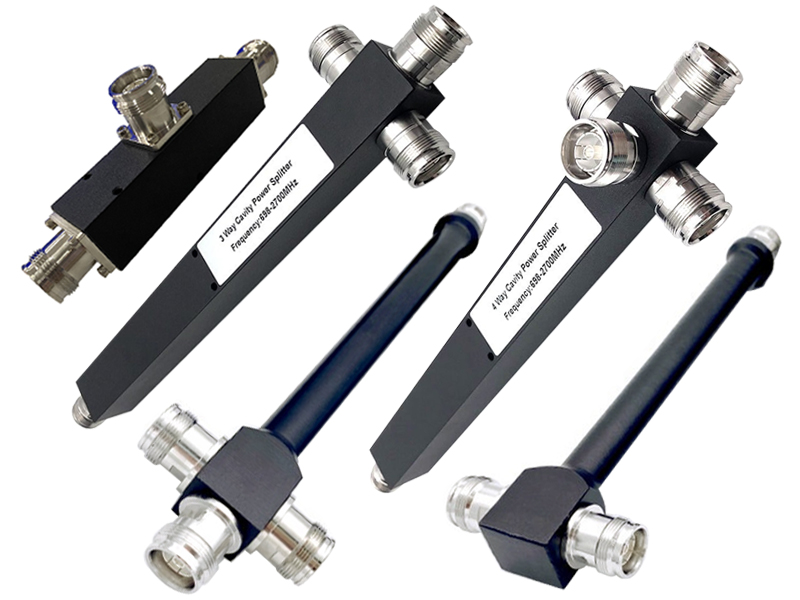
4.3-10 splitters are available in a range of port counts to match system requirements.
| Port Count | Theoretical Split Loss | Common Applications |
| 2-way | 3.0 dB | Most common; sector feeds, small cell distribution |
| 3-way | 4.8 dB | Three-sector base stations, specific antenna feeds |
| 4-way | 6.0 dB | Indoor DAS, multi-antenna systems |
| 6-way | 7.8 dB | Medium-scale distribution in buildings |
| 8-way | 9.0 dB | Large DAS nodes, campus distribution |
| 12-way / 16-way | 10.8 / 12.0 dB | High-density distribution networks |
Higher port counts are typically realized by cascading multiple 2-way Wilkinson stages within a single housing. The 4.3-10 connector's compact size makes such multi-way splitters physically smaller than their 7/16 DIN equivalents, facilitating installation in crowded equipment cabinets.
Power handling for 4.3-10 splitters spans a range suited to various deployment scenarios.
Low-power (10–30 W): Common in small cells, indoor DAS, and remote radio head (RRH) feeds where transmit power is modest.
Medium-power (30–100 W): Standard for macro-cell base stations and outdoor DAS nodes.
High-power (100–300 W): Used in high-power macro cells, broadcast applications, and some radar systems. These units often incorporate enhanced thermal management, such as finned housings.
The 4.3-10 connector itself is rated for average power up to several hundred watts at lower frequencies, making it suitable for most cellular infrastructure applications.
4.3-10 splitters are designed to cover specific frequency bands critical to wireless communications.
Low-band (698–960 MHz): Covers LTE bands 5, 8, 12, 13, 14, 17, 20, etc.
Mid-band (1710–2700 MHz): Covers PCS, AWS, DCS, LTE bands 1, 2, 3, 4, 7, 25, 66, 40 (2300 MHz), etc.
High-band (3400–4200 MHz): Covers C-band for 5G and some 5G mid-band deployments.
Broadband (698–2700 MHz or 698–3800 MHz): Single splitter covering most sub-4 GHz cellular bands, simplifying inventory and installation.
Full-band (DC–6 GHz): Typically resistive designs used in test applications rather than infrastructure.
Many infrastructure-grade 4.3-10 splitters are dual-band or tri-band, designed to cover low and mid bands (e.g., 698–2700 MHz) with excellent performance across the entire range.
Passive Intermodulation (PIM) is a critical performance metric for splitters used in multi-carrier, multi-operator environments. PIM occurs when two or more high-power transmit signals mix in a passive nonlinearity (e.g., a poor connection, ferromagnetic material, or improperly plated surface), creating unwanted interference that can fall into receive bands and desensitize receivers.
4.3-10 splitters are classified into PIM grades:
Standard PIM: –150 dBc or better (sometimes –153 dBc). Suitable for single-operator or lower-capacity sites.
Low PIM: –155 dBc to –158 dBc. Common for general infrastructure.
Ultra-Low PIM: –160 dBc or better. Required for high-density, multi-operator sites and for low-band systems (e.g., 700 MHz) where PIM products are more problematic.
Because the 4.3-10 interface was designed from the ground up for low-PIM performance (unlike adapted legacy connectors), high-quality splitters routinely achieve –160 dBc PIM performance when properly manufactured and assembled.
Selecting a 4.3-10 power splitter requires careful evaluation of several electrical and mechanical parameters. The table below summarizes typical specifications for a high-performance infrastructure-grade Wilkinson splitter covering 698–2700 MHz.
| Parameter | Typical Specification | Notes |
| Frequency range | 698–2700 MHz, 698–3800 MHz, or band-specific | Coverage of cellular bands |
| Insertion loss (2-way) | ≤ 3.3 dB (typically 3.2 dB) | Theoretical split loss is 3.0 dB |
| Excess loss | ≤ 0.3 dB | Loss above theoretical |
| Amplitude balance | ±0.3 dB (typical ±0.2 dB) | Variation between outputs |
| Phase balance | ±3° (typical ±2°) | Phase difference between outputs |
| Isolation (output to output) | ≥ 20 dB (typically 25 dB) | Prevents crosstalk |
| Input VSWR | ≤ 1.25:1 (typical 1.20:1) | Impedance match at input |
| Output VSWR | ≤ 1.25:1 (typical 1.20:1) | Impedance match at outputs |
| PIM (2×20 W carriers) | ≤ –160 dBc (typical –165 dBc) | For low-PIM grades |
| Average power handling | 30 W, 50 W, 100 W, or 200 W CW | Derate at elevated temperature |
| Operating temperature | –40°C to +85°C (or –55°C to +125°C for premium) | Outdoor infrastructure rating |
| Impedance | 50 Ω | Standard for RF systems |
| Connector interface | 4.3-10 female (or male on input) | Per IEC 61169-54 |
Insertion Loss and Excess Loss
Insertion loss is the total signal power lost from input to output. For a 2-way splitter, at least 3.0 dB is unavoidable because power is divided equally. Any additional loss—excess loss—represents inefficiency in the splitter's transmission lines, resistors, and connectors. Low excess loss is critical in remote radio head applications where every decibel of transmit power is valuable.
VSWR (Voltage Standing Wave Ratio)
VSWR measures impedance match quality. A low VSWR (close to 1.00:1) ensures that maximum power is transferred and reflections are minimized. Poor VSWR can cause ripple in frequency response, reduce coverage, and potentially damage transmitters. For 4.3-10 splitters, VSWR ≤ 1.25:1 is standard; precision units achieve ≤ 1.15:1.
Isolation
Isolation between output ports prevents a signal applied to one output from appearing at another. In a typical base station, one output might connect to an antenna while another connects to a receiver for diversity or monitoring. High isolation ensures the transmitter signal does not leak into and desensitize the receiver. 20 dB isolation reduces leakage by a factor of 100; 30 dB reduces it by a factor of 1000.
PIM (Passive Intermodulation)
PIM is expressed in dBc (decibels relative to the carrier). A specification of –160 dBc means that the third-order intermodulation product is 160 dB below one of the two input carriers (each at, say, +43 dBm). Achieving –160 dBc requires meticulous design: non-ferromagnetic materials (brass, stainless steel, PTFE), proper plating (silver or low-PIM nickel), and clean, precise assembly. 4.3-10 splitters are inherently suited to low-PIM because the connector interface was designed without ferrous components and with robust mechanical contact.
Amplitude and Phase Balance
These parameters describe how closely the outputs match each other. For MIMO (Multiple-Input Multiple-Output) systems and phased arrays, amplitude and phase consistency across splitter outputs directly affects beamforming accuracy and spatial multiplexing performance. Typical specifications of ±0.3 dB and ±3° are adequate for most applications; precision versions offer ±0.1 dB and ±1°.
Power Handling and Derating
The specified average power rating applies at room temperature (typically +40°C, sometimes +25°C). At higher temperatures, the splitter's ability to dissipate heat decreases, so the allowable input power must be derated. A typical derating curve linearly reduces power handling from 100% at +40°C to 50% at +85°C. For pulsed applications, peak power can be much higher (e.g., 1 kW peak for 10 μs pulse) as long as average power remains within limits.
Environmental and Mechanical Robustness
4.3-10 splitters intended for outdoor use are typically rated for IP65 or IP67 when mated, protecting against dust and water jets or temporary immersion. The operating temperature range of –40°C to +85°C covers most global outdoor environments. Some industrial-grade splitters extend to –55°C to +125°C.
The following table provides a quick reference for selecting a 4.3-10 power splitter based on application needs.
| Application | Recommended Topology | Port Count | Power Handling | PIM Grade | Key Focus |
| Macro cell base station | Wilkinson | 2-way, 3-way, 4-way | 100–200 W | –160 dBc | Low loss, high isolation, low PIM |
| Small cell / micro cell | Wilkinson | 2-way, 4-way | 30–50 W | –155 dBc | Compact size, cost-effective |
| Indoor DAS | Wilkinson | 4-way, 6-way, 8-way | 10–30 W | –150 dBc | Many outputs, easy installation |
| Public safety / first responder | Wilkinson | 2-way, 4-way | 50–100 W | –160 dBc | Reliability, wide temperature range |
| Test lab / characterization | Resistive (or precision Wilkinson) | 2-way, 4-way | 1–10 W | Not critical | Ultra-wideband, amplitude flatness |
When comparing power splitters, the choice of connector interface has significant implications. The 4.3-10 offers distinct advantages:
| Feature | 4.3-10 | 7/16 DIN | N-Type | SMA |
| Size | Small (50% smaller than 7/16) | Large | Medium | Very small |
| Port density | High | Low | Medium | Very high |
| Power handling | High (100–300 W) | Very high (500+ W) | Medium (50–200 W) | Low (1–50 W) |
| PIM performance | Excellent (≤ –165 dBc) | Excellent | Good | Poor to fair |
| Frequency range | DC–6 GHz (optimized for sub-6) | DC–7.5 GHz | DC–11/18 GHz | DC–18/26.5 GHz |
| Torque | 1.0–1.5 Nm | 3.0–3.5 Nm | 1.0–1.5 Nm | 0.7–0.9 Nm |
| Weatherproofing | Good (IP67 possible) | Excellent | Good | Poor (usually indoor) |
For modern sub-6 GHz 5G deployments, the 4.3-10 splitter hits a sweet spot: sufficient power handling for macro sites, excellent PIM performance, compact size for dense panels, and standardized torque for reliable installation.
To ensure optimal performance from a 4.3-10 power splitter:
Use proper torque: 4.3-10 connectors require 1.0–1.5 Nm (approximately 9–13 in-lbs). Over-torquing can damage the interface; under-torquing can cause PIM and poor contact.
Terminate unused ports: Always cap or terminate unused output ports with a 50 Ω load (preferably a low-PIM terminator) to prevent reflections.
Keep connectors clean: Contamination (dirt, oil, or oxidation) is a primary cause of PIM. Use IPA wipes and PIM-safe cleaning tools.
Avoid ferromagnetic materials: Never use steel tools or components near the RF path; use brass, stainless steel (non-magnetic), or aluminum hardware.
Observe power derating: Reduce input power when operating in high-temperature environments.
Verify PIM before deployment: For critical sites, test the installed splitter's PIM performance to confirm it meets specifications.
As the wireless industry evolves, 4.3-10 splitters are also advancing:
Extended frequency range: New designs push beyond 6 GHz to support 5G mid-band expansions (e.g., 6–7 GHz bands being auctioned in some regions).
Higher integration: Splitters are increasingly combined with other components (filters, diplexers, bias-Ts) into single multi-function modules.
Ultra-low PIM materials: Advances in plating technology (silver, low-PIM nickel, and specialized alloys) push PIM performance below –170 dBc.
Smart splitters: Some emerging products include monitoring circuitry (e.g., power detectors) while maintaining passive integrity.
Environmental hardening: IP68-rated splitters suitable for direct burial or submersion are becoming more common for DAS and tower-top applications.