


-
We’re On Call 24/7 : +8613538296050
-
E-mail : anna@rohoconnector.com
We’re On Call 24/7 : +8613538296050
E-mail : anna@rohoconnector.com
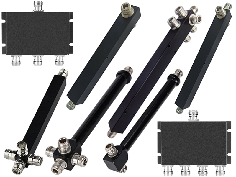
In the demanding world of RF and microwave engineering, signal distribution is a task that requires precision, reliability, and often, significant power handling. Among the many connector interfaces available, the N-Type stands out for its rugged construction, excellent electrical performance, and ability to handle higher power levels than its smaller counterparts like SMA. N-Type power splitters (also known as power dividers) leverage these advantages, making them the go-to choice for telecommunications infrastructure, broadcast systems, high-power test environments, and aerospace applications.
This blog explores the classification and key performance characteristics of N-Type power splitters, providing engineers with the knowledge needed to select the optimal component for their systems.
An N-Type power splitter is a passive device that takes a single RF input signal and divides it into two or more outputs, all while maintaining proper impedance matching (typically 50 Ω). The N-Type connector, characterized by its threaded coupling mechanism and robust internal construction, was originally developed for military applications and has since become a standard for systems requiring durability and performance from DC to 11 GHz (with precision versions reaching 18 GHz).
The primary functions of an N-Type power splitter include:
Evenly distributing a signal to multiple paths (e.g., feeding multiple antennas from one transmitter)
Combining signals from multiple sources (when used as a combiner, thanks to reciprocity)
Providing test points in a system without disrupting the main signal path
Enabling parallel processing of signals in test and measurement setups
N-Type power splitters are classified according to several criteria: circuit topology, port count, power handling, and frequency range. Understanding these categories is essential for matching the component to the application.
The internal design of a power splitter dictates its performance trade-offs. Two primary topologies dominate the N-Type landscape.
Wilkinson Power Splitters
Named after Ernest Wilkinson who described the design in 1960, this topology is the industry standard for applications requiring low insertion loss and high isolation between output ports. A Wilkinson splitter uses quarter-wave transmission lines and internal isolation resistors to achieve excellent matching and port-to-port isolation.
Key characteristics:
Low insertion loss: Excess loss typically 0.1–0.5 dB above the theoretical split loss
High isolation: 20–30 dB between output ports, preventing crosstalk
Good VSWR: Typically 1.2:1 to 1.5:1 at all ports
Matched outputs: All output ports present the same impedance to the source
Frequency limited: Best performance over octave or multi-octave bands
Wilkinson splitters are ideal for telecommunications, cellular base stations, and any system where signal integrity and isolation are critical.
Resistive Power Splitters
Resistive designs employ a simple network of precision thin-film resistors to divide the signal. While they introduce higher insertion loss (typically 6–8 dB for a 2-way split, compared to the theoretical 3 dB split loss), they offer unique advantages.
Key characteristics:
Ultra-wide bandwidth: Operate from DC to frequencies exceeding 18 GHz
Higher insertion loss: 3–5 dB excess loss above theoretical split loss
Moderate isolation: Typically 6–10 dB between outputs
Excellent return loss: Good matching at all ports due to the resistive network
Amplitude flatness: Very stable across frequency
Resistive splitters are preferred for broadband test systems, laboratory instrumentation, and applications where extreme frequency coverage outweighs efficiency concerns.
Hybrid (Quadrature) Splitters
A less common but important category is the 90-degree hybrid coupler used as a splitter. These devices divide power equally with a 90-degree phase difference between outputs. They are essential for image-reject mixers, I/Q modulators, and phased-array feed networks. N-Type hybrids are available for frequencies typically up to 2–3 GHz due to physical size constraints.
N-Type power splitters are available with various numbers of output ports, each configuration having its own performance implications.
| Port Count | Theoretical Split Loss | Typical Applications |
| 2-way | 3.0 dB | Most common; base station feeds, test setups |
| 3-way | 4.8 dB | Unequal sector coverage, specialized distribution |
| 4-way | 6.0 dB | Multi-antenna systems, indoor DAS |
| 6-way | 7.8 dB | Medium-scale distribution networks |
| 8-way | 9.0 dB | Large antenna arrays, laboratory distribution |
| 12/16-way | 10.8 / 12.0 dB | High-density distribution, broadcast systems |
Higher port counts are typically constructed by cascading 2-way Wilkinson stages, resulting in increased insertion loss and larger physical size.
The robust N-Type interface allows for significantly higher power handling than smaller connectors like SMA. Classification by power is essential for safety and reliability.
Low-power (1–10 watts): Suitable for receiver distribution, signal-level test setups, and indoor infrastructure
Medium-power (10–50 watts): Common in small-cell base stations, low-power transmitters, and general-purpose RF systems
High-power (50–200 watts): Used in macro-cell base stations, broadcast transmitters, and industrial RF systems
Very high-power (200–500+ watts): Specialized designs with enhanced thermal management for high-power broadcast and radar
Higher power ratings require larger housing with finned heat sinks, careful internal construction, and sometimes forced-air cooling.
While 50 Ω is the standard for most RF and telecommunications systems, 75 Ω N-Type splitters exist for video broadcast and CATV applications. However, true 75 Ω N-Type connectors are rare; most 75 Ω systems use BNC or F-type connectors.
N-Type splitters span a wide range of operating bands:
DC–1 GHz: Legacy and broadcast applications
DC–3 GHz: Cellular (2G/3G/4G), public safety, and industrial bands
DC–6 GHz: Modern 5G sub-6 GHz, Wi-Fi 6/6E
DC–11 GHz: Standard N-Type performance limit; radar and satellite bands
DC–18 GHz: Precision N-Type splitters for microwave applications
When selecting an N-Type power splitter, engineers must evaluate a set of critical electrical and mechanical parameters. The table below summarizes the typical specifications for different grades.
| Parameter | Standard Grade | Precision Grade | Notes |
| Frequency range | DC–6 GHz | DC–11 GHz (or 18 GHz) | Higher frequency requires tighter tolerances |
| Insertion loss (2-way) | 3.3–3.6 dB | 3.1–3.2 dB (Wilkinson) | Theoretical split loss is 3.0 dB |
| Excess loss (Wilkinson) | 0.3–0.6 dB | 0.1–0.2 dB | Loss above theoretical |
| Resistive insertion loss (2-way) | 6.5–7.5 dB | 6.0–6.5 dB | Higher but ultra-wideband |
| Isolation | 20–25 dB | 25–30 dB (Wilkinson) | Lower for resistive |
| Input VSWR | 1.3:1 – 1.5:1 | 1.15:1 – 1.25:1 | Lower is better |
| Output VSWR | 1.3:1 – 1.5:1 | 1.15:1 – 1.25:1 | Match at all outputs |
| Amplitude balance | ±0.3–0.5 dB | ±0.1–0.2 dB | Consistency between outputs |
| Phase balance | ±3° – 5° | ±1° – 2° | Critical for coherent systems |
| Power handling (CW) | 10–50 W | 50–200 W | Depends on housing and design |
| Operating temperature | -40°C to +85°C | -55°C to +125°C | Wider range for military/aerospace |
Insertion Loss
This is the total signal power lost from input to output. For a 2-way splitter, the unavoidable 3.0 dB is due to splitting the power equally. Any additional loss (excess loss) comes from conductor resistance, dielectric losses, and impedance mismatches. Low insertion loss is critical for preserving signal-to-noise ratio in receive paths and minimizing wasted power in transmit paths.
Isolation
Isolation measures how much of a signal applied to one output port appears at another output port. High isolation prevents interference between receivers connected to different outputs. In a base station, for example, a high-power transmitter on one output could desensitize a receiver on another output if isolation is poor.
VSWR (Voltage Standing Wave Ratio)
VSWR indicates how well the splitter's ports are matched to 50 Ω. A VSWR of 1.00:1 is perfect; 1.25:1 corresponds to a return loss of 19 dB (2.5% reflected power). Poor VSWR leads to signal reflections that can cause ripples in frequency response, reduce power transfer, and potentially damage sources.
Amplitude and Phase Balance
For systems using multiple channels coherently—such as phased array antennas, MIMO radios, and I/Q modulators—the matching of amplitude and phase between splitter outputs is paramount. Amplitude imbalance causes unequal power distribution, while phase imbalance distorts beamforming and demodulation.
Power Handling and Thermal Management
Power rating is specified as maximum continuous wave (CW) input power. For pulsed applications, peak power can be orders of magnitude higher. N-Type splitters used in high-power environments often feature finned aluminum housings, thermal pads, and sometimes cooling fans. Derating curves apply at elevated temperatures.
Frequency Response Flatness
The variation in insertion loss across the specified frequency range. Good splitters exhibit flatness of ±0.2 dB or better. Poor flatness can distort signals, especially wideband modulations like 5G NR and OFDM.
Understanding where N-Type power splitters excel helps guide selection.
Cellular Base Stations (Macro Cells)
Requirement: Split transmitter power to multiple antennas (e.g., 3 sectors)
Choice: 3-way Wilkinson splitter, 50–500 W power handling, low insertion loss
Key specs: Low VSWR, high isolation, outdoor temperature rating
Distributed Antenna Systems (DAS)
Requirement: Distribute signal to many antennas in a building or tunnel
Choice: 4-way, 6-way, or 8-way splitters cascaded
Key specs: Moderate power (10–50 W), good amplitude balance, compact size
Test Laboratories
Requirement: Split a reference signal to multiple instruments
Choice: Resistive splitter for DC–18 GHz coverage, or Wilkinson for better isolation
Key specs: Wide bandwidth, excellent return loss, phase stability
Broadcast Transmitters
Requirement: Feed multiple transmitters or antennas from a single exciter
Choice: High-power (100–500 W) Wilkinson splitters with thermal management
Key specs: Low insertion loss, high isolation to prevent intermodulation
Radar Systems
Requirement: Distribute pulsed high-power signals to array elements
Choice: High-power N-Type splitters with peak power rating
Key specs: Low VSWR, phase-matched outputs, rugged construction
Engineers can follow this decision framework to select the optimal splitter for their application.
| Application Priority | Recommended Topology | Key Specifications to Check |
| Minimum insertion loss | Wilkinson | Excess loss, VSWR |
| Wide bandwidth (DC–18 GHz) | Resistive | Insertion loss (accept higher loss) |
| High isolation | Wilkinson | Isolation > 25 dB |
| High power (>50 W) | Wilkinson (with thermal design) | Power rating, VSWR, temperature range |
| Excellent amplitude/phase match | Wilkinson (precision grade) | Amplitude balance, phase balance |
| Cost-sensitive, low frequency | Resistive or simple Wilkinson | Basic specs, no frills |
| Outdoor / harsh environment | Either, with IP rating | Temperature range, sealing, corrosion resistance |
Always verify that the splitter's frequency range covers your entire operating band, including any harmonics or spurious signals that could cause issues. Derate power ratings by 20–30% for continuous operation near the maximum temperature.
To ensure long-term reliability and performance:
Use proper torque: N-Type connectors require 12–15 in-lbs (1.4–1.7 Nm) torque for consistent connection
Protect unused ports: Always terminate unused outputs with a 50 Ω N-Type load to prevent reflections
Observe power derating: Reduce input power when operating at elevated temperatures
Avoid mechanical stress: Support heavy splitters to prevent strain on connectors
Keep connectors clean: Use isopropyl alcohol and lint-free swabs for cleaning
Inspect regularly: Check for corrosion, pitting, or damaged threads
The N-Type power splitter market continues to evolve:
Higher frequencies: Precision N-Type designs now reliably reach 18 GHz, pushing the traditional 11 GHz limit
Improved thermal management: New alloys and heat sink geometries allow higher power in smaller packages
Integration: Some splitters now include DC-passing or DC-blocking options, or integrate filters
Low-PIM designs: For multi-carrier cellular systems, low passive intermodulation (PIM) N-Type splitters are increasingly common
Ruggedized for outdoor: IP67-rated splitters with weather-sealed connectors for tower-top deployments