

-
We’re On Call 24/7 : +8613538296050
-
E-mail : anna@rohoconnector.com
We’re On Call 24/7 : +8613538296050
E-mail : anna@rohoconnector.com
There is a particular kind of engineering decision that looks trivial on a schematic but quietly determines whether a radio works at all: the choice of the tiny coaxial connector that carries the antenna signal off the PCB. The IPEX connector—known generically as MHF, U.FL-compatible, or “the little snap-on RF connector”—is that decision. It occupies a few square millimeters of board space, yet it must preserve a 50-ohm impedance path, survive repeated mating, and stay electrically transparent from DC to frequencies that now reach into the millimeter-wave region.
The IPEX family is not a single connector. It is a lineage. Understanding that lineage is the difference between a design that fits and a design that fails quietly at 6 GHz.
One Name, Several Lineages
“IPEX” is used loosely in the industry to describe an entire class of ultraminiature board-to-antenna coaxial connectors. Strictly speaking, the original interface standard was established by one connector maker, while the MHF designation belongs to another manufacturer’s compatible product line. The first MHF variant was designed as a direct, footprint-compatible alternative to the de facto U.FL standard; later generations diverged in size and performance, and are not footprint-interchangeable with the original.
For the engineer, the practical takeaway is simpler: when a datasheet says “IPEX” or “MHF,” the generation number matters more than the brand name. The same three letters describe connectors that differ by a factor of nearly two in mated height and by an order of magnitude in usable bandwidth.
Classification: The Generation Ladder
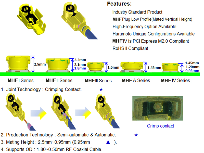
The IPEX/MHF family is best classified by generation, because each step down the ladder represents a deliberate trade: smaller footprint and lower profile, in exchange for tighter manufacturing tolerance, higher precision cable, and—in most cases—loss of backwards compatibility.
MHF1 / IPEX 1st Generation: The Baseline
The first generation established the mechanical and electrical template. It uses a terminal diameter of approximately 2.0 mm, a mated height below 3.0 mm, and a PCB footprint around 3.0 × 3.1 mm. Electrical performance is modest by modern standards: DC to 6 GHz, sufficient for Wi-Fi, Bluetooth, and GPS in general-purpose IoT devices. Its defining virtue is compatibility—MHF1 remains mechanically interchangeable with the long-standing U.FL interface, which is why it persists in routers, industrial PCs, and legacy network cards.
A second-generation variant reduced mated height to under 2.1 mm while keeping the same terminal diameter, yielding a slightly lower-profile package for thin laptops and portable terminals.
MHF3 / IPEX 3rd Generation: The High-Frequency Turning Point
The third generation is where the family stopped being a commodity connector and became a high-frequency component. The terminal diameter dropped to roughly 1.4 mm, mated height to below 1.6 mm, and the PCB footprint to 1.7 × 1.7 mm. More importantly, the internal contact design changed to a tighter inner-pin arrangement, reducing signal loss and interference at higher frequencies.
The performance envelope reflects that redesign: usable to 6 GHz, with VSWR typically specified as 1.3 maximum from DC to 3 GHz and 1.45 to 1.5 maximum from 3 to 6 GHz. This is the generation that made IPEX connectors credible for Wi-Fi 6 and sub-6 GHz 5G front ends, where a few tenths of a dB of mismatch loss at the antenna port can visibly reduce range and throughput.
MHF4 and MHF4L / IPEX 4th Generation: The Compact Workhorse
The fourth generation is arguably the most widely deployed in current compact wireless designs. The terminal diameter is approximately 1.5 mm, mated height can be as low as 1.2 mm, and the receptacle body is around 2.0 × 2.0 mm. The frequency ceiling moves decisively upward.
The standard MHF4 is specified to roughly 10 GHz, while the MHF4L variant extends to 12 GHz with a maximum VSWR of 1.45 and a 50-ohm characteristic impedance. It supports micro-coaxial cables in the AWG 30 to AWG 36 range, with outer diameters from about 0.95 mm to 1.37 mm, and operates over a −40 °C to +90 °C service window. One notable assembly feature is a solderless termination technology that simplifies attachment of extremely fine coax without the thermal risk of hand soldering.
MHF4 is not footprint-compatible with U.FL, and that incompatibility is intentional: the smaller geometry is what buys the lower profile and higher frequency capability.
MHF5 and MHF5L / IPEX 5th Generation: The Millimeter-Wave Edge
The fifth generation pushes the family toward the frequencies associated with 5G millimeter-wave, high-resolution radar, and dense small-cell radios. MHF5L is specified from DC to 15 GHz with a mated height of 1.0 mm or 1.3 mm depending on the variant, and accepts cables down to 0.48 mm outer diameter (AWG 38). The VSWR curve illustrates the reality of operating this close to the interface limit: typically 1.3 maximum to 3 GHz, rising to around 1.8 at 9–12 GHz.
The MHF5 generation is not a universal drop-in replacement for earlier variants. It is a specialist interface for designs where every fraction of a millimeter and every gigahertz of bandwidth matters, and where the assembly process can hold the tolerances that the connector demands.
The Performance Characteristics That Actually Matter
Frequency Range and VSWR
Frequency capability is the headline differentiator, but VSWR is the more honest specification. An IPEX connector that “works to 12 GHz” is not equally transparent across that band. The practical figure of merit is the VSWR at the specific operating frequency, and it degrades as the connector approaches its upper limit. For a 2.4 GHz Wi-Fi link, even a first-generation part can be adequate; for a 10 GHz radar front end, only a fourth- or fifth-generation interface with a controlled VSWR specification is appropriate.
Impedance and Cable Compatibility
Every generation in the family is a 50-ohm interface. That is non-negotiable: the connector, the mating pigtail, and the PCB launch must all present 50 ohms, or the resulting mismatch will show up as reflected power, reduced range, and—in extreme cases—regulatory emission failures.
Cable compatibility is the quiet constraint. MHF3 and earlier generally pair with conventional micro-coax in the AWG 32–36 range. MHF4 supports AWG 30–36. MHF5L reaches down to AWG 38, with outer diameters approaching 0.48 mm. The smaller the cable, the more fragile the assembly and the more demanding the termination process. A connector that is electrically ideal can still fail in production because the cable handling window is too narrow.
Mated Height and PCB Real Estate
The generational shrinkage is dramatic when expressed in board-level terms. MHF1 occupies roughly 3.0 × 3.1 mm and stands about 2.5 mm tall when mated. MHF2 reduces the footprint to 2.0 × 2.0 mm and mated height to around 1.4 mm. MHF3 reaches 1.7 × 1.7 mm and approximately 1.3 mm mated height. MHF4 holds a similar footprint but can mate as low as 1.2 mm, and MHF5L reaches 1.0 mm. In a smartwatch, a true wireless earbud, or a densely populated 5G module, those tenths of a millimeter determine whether the enclosure closes.
Mechanical Durability and Mating Cycle Life
IPEX connectors are snap-on interfaces, and they are not intended for frequent cycling. Standard durability is commonly specified in the range of tens of mating cycles for the basic interface, with high-cycle variants available for test fixtures and production programming. The practical rule is simple: choose the connector for the product’s assembly and service model, not for a laboratory habit of repeated connects. If the antenna must be swapped repeatedly, a threaded interface belongs in the design, not a push-on micro-coax connector.
Shielding and Grounding
The electrical quality of an IPEX launch depends as much on the PCB ground ring as on the connector body. The outer shell must contact a well-designed, continuous ground reference around the receptacle. A perfect connector soldered to a fragmented ground plane will still leak, resonate, or produce unpredictable VSWR. This is the most common hidden failure mode in compact RF layouts, and it is invisible on a bill of materials.
A Selection Framework, Not a Shopping List
Choosing an IPEX generation is not a matter of picking the newest or the smallest. It is a three-variable optimization: frequency ceiling, mechanical envelope, and manufacturability.
A general-purpose Wi-Fi, BLE, or GPS design in a router or industrial terminal is well served by the first or second generation, where U.FL compatibility and broad cable availability reduce sourcing risk. A thin laptop, tablet, or compact IoT module points to the third generation, where the footprint shrinks while the electrical performance remains adequate for sub-6 GHz systems. A 5G sub-6 module, a drone radio, or a wearable with tight z-height constraints calls for the fourth generation, provided the assembly house can handle the finer cable. And a millimeter-wave or high-band 5G front end, where the interface must remain usable to 12–15 GHz, justifies the fifth generation—along with the tighter process control that comes with it.
The connector does not amplify, filter, or process the signal. It only has to stay out of the way. In the IPEX family, staying out of the way is an exercise in matching millimeters to megahertz, and generations to manufacturing reality.
Tags :