Factors affecting the performance of RF coaxial cable connector
Mar 04, 2019
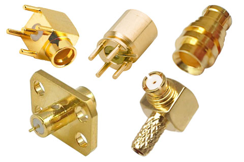
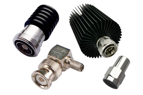
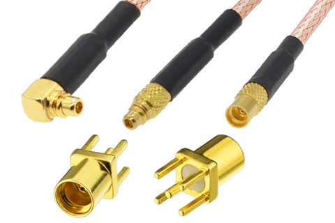
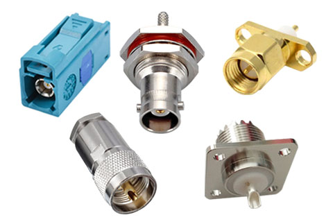
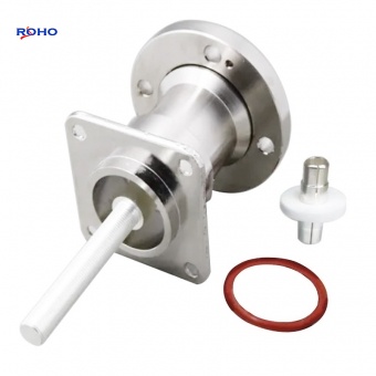
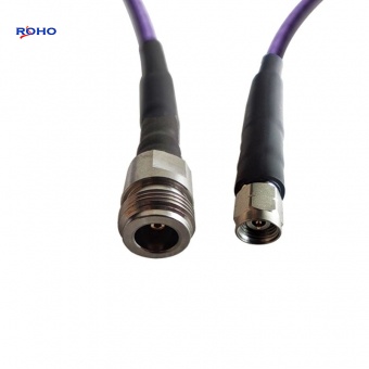
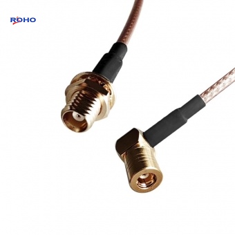
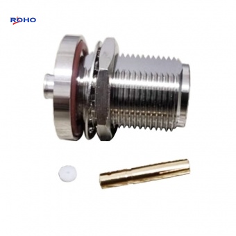
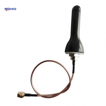
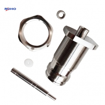
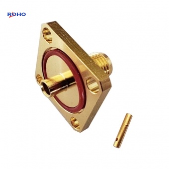
In the connector field, the RF coaxial connector is a subdivided category, while under the rf coaxial connector category, there are also related products about the rf coaxial cable connector components. What is an rf coaxial cable connector assembly and how its performance is affected? ROHO will give you some basic knowledge of the rf coaxial cable connector assembly. It must be clear to those who are engaged in connector manufacturing that the components of the rf coaxial connector cable are composed of two rf coaxial connectors and a certain length of the rf coaxial cable through welding. Therefore, the rf coaxial cable becomes an indispensable part of the rf coaxial cable connector assembly, and its performance is directly related to the performance of the rf coaxial cable connector assembly. It is concluded that the following six main factors influencing the performance of rf coaxial cable connector components are as follows: 1, The standing wave has bad periodicity. 2, Poor performance due to local deformation; 3, Impedance mismatch (high or low ); 4, The movement between the cable foaming layer and the outer conductor; 5, The foaming layer is pasted on the inner conductor and cannot be cleaned; 6, The inner conductor size does not meet the requirements; The six points above are the mainly influences of the performance of the Rf coaxial cable connector assembly. So the way to enhance the ability of them is that we need to reduce the six failure modes. Meanwhile, the dimension of the inner rf connector must meet the requirement. When we find the failure modes of Rf coaxial cable assembly, that means we also find the direction of improving the performance of them. It is of great guiding significance to improve the performance of rf coaxial cable in major manufacturers. In addition, ROHO provide you with several ways to improve cable performance, for your reference as below: First of all, the selection of internal and external conductor materials should be done well, that is to say, the model and impedance of internal and external conductor and rf connector should be unified. Secondly, in the process of extruding insulation, we should control the foaming uniformity to a high standard, and improve the diameter uniformity of the foaming insulation wire core and the stability of capacitance. The third is to improve the concentricity of the inner and outer conductors, that is, to control the insulation of cables without eccentricity. Finally, the tolerance requirement of inner conductor should be strictly controlled.
View details