News
  • The role and development prospects of RF connectors
    The role and development prospects of RF connectors Nov 03, 2014
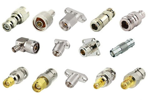
        RF connectors can be far and near in people’s lives, but in our daily life, they are inseparable from RF connectors. They play a major role in our daily lives, so we can learn more and Learn about RF connectors.     In addition to the requirements of general characteristics, RF coaxial connectors also have a very key requirement that they must be good in touch, reliable in work, and convenient in maintenance. The reliability of the work of the radio frequency connector will immediately endanger all the normal work of the airport power circuit, and even the misfortune of all the hosts. Therefore, the host power circuit has very strict requirements for the quality and stability of the radio frequency connector.     Therefore, the high quality and high reliability of the radio frequency connector make it widely used in aviation, aerospace, national defense and security and other military system software.     There are three common classifications of radio frequency connectors: appearance design, structure, and main purpose.     1. Appearance design     Circular RF connector: mostly used in military equipment (such as airlines, aerospace)     Rectangular RF connector: simple structure, mostly used for printed pcb circuit boards of electronic products      2. Structure     The composition of the fixed-end radio frequency connector (female contact-power socket) and the free end radio frequency connector (male contact-power plug). The power socket is fixed on the power consumption component according to its square (circle) plate (some or welding methods are selected). The power plug is generally connected to the cable, and the power plug and the power socket are connected according to the docking screw cap.     Structural features of radio frequency connector: resistant to natural environment, interface type (rapid) docking, multi-button (error insertion prevention), touch body     The three basic elements of the radio frequency connector are composed of the shell, the conductor and the insulator, the contact body and the transmission line riveting butt, (single root is easy to solve the common fault).     1) Shell     Refers to the housing, connection screw cap, and end fittings of the socket plug.     The function of the case is to protect the internal components of the radio frequency connector such as the conductor, the insulator, and the contact body (collectively called the pin socket) from being damaged. The precise positioning key slot on the top ensures the precise positioning of the power plug and the power socket. The connecting screw cap is used to connect and separate the power plug socket. The end fittings are used to maintain the connection between the power line and the touch body line from being damaged and to fix the cable.     The shell has the function of a certain magnet...
    View details

  • Influencing factors of attenuation of RF coaxial cable
    Influencing factors of attenuation of RF coaxial cable Oct 06, 2014
        Abstract: The rapid development of mobile communications has increased the demand for RF coaxial cables. Therefore, analyzing the attenuation factors of coaxial cables is of great significance to our scientific decision-making.     This article focuses on the analysis of factors that affect the attenuation of RF coaxial cables, including raw materials, standing wave cable structure and temperature. I. Overview     Attenuation is one of the most important parameters of radio frequency cables. It reflects the loss of electromagnetic energy during cable transmission.     The attenuation of the cable indicates the degree of power transmission or voltage loss when the cable is working in the traveling wave state.     The greater the attenuation of the cable, the more serious the signal loss, and the worse the transmission efficiency of the cable. If the total attenuation of the cable is equal to 3dB, it means that the current or voltage amplitude of the signal bath after the cable is transmitted is reduced by about 30%, and the signal power Decrease by 50%.     Therefore, the attenuation of the cable is a very important indicator. This is especially true for long-length transmission. In order to reduce the attenuation of the cable, a considerable cost must be drawn economically.     When choosing a cable, it cannot be considered that the lower the attenuation, the better, but this index and other factors must be considered comprehensively to select an economical and suitable cable.      2. Overview of factors affecting the attenuation of RF coaxial cables     RF cables are mainly composed of conductors, insulation, sheaths and armors. Among them, the conductors play the guiding role of electrical signals. Insulation is the medium on which electrical signals are transmitted. Sheath and armor are necessary for conductors and insulation. The protection of the cable makes the finished cable endure the effects of various use environments.     Therefore, the main factors affecting RF coaxial cables can be summarized into three categories: raw materials, cable structure and temperature.     1. Raw materials     1.1 Insulation layer     Insulation is the medium for radio frequency signal transmission. The material and structure of the insulation are required to ensure the lowest possible loss of the cable, and it must also have sufficient mechanical strength to keep the inner and outer conductors in the coaxial position. The radio frequency cable insulation can be divided into solid, air and semi-core. Air insulation.     The influence of insulation on the attenuation is smaller, but its influence continues to increase as the frequency increases. When it reaches the 2GHz frequency band, the attenuation of the medium cannot be ignored.     Since the insulation layer basically adopts a foamed structure, f...
    View details
  • About the Naming Method of RF Connector
    About the Naming Method of RF Connector Sep 01, 2014
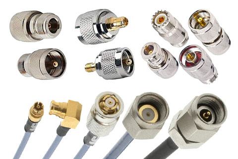
        RF coaxial connectors are abbreviated as RF connectors. You know it. It is generally considered as an element attached to a cable or to an installation instrument as an electrical connecting or separating element of the transmission line. It belongs to mechatronic products. In simple terms, it serves as a bridge.     First,the radio frequency connector naming method     The model of the universal RF connector consists of two parts: the main code and the structure form code. The middle is separated by a dash "-". Other conditions that need to be specified can be specified in the detailed specification and separated by a dash.     Second, RF connector code description.     1. 17 kinds of appearance code introduction      (1)  Type N: Threaded RF coaxial connectors with an inner diameter of the outer conductor of 7mm (0.276 inch) and a characteristic impedance of 50 ohms (75 ohms). (IEC169-16)     (2)  BNC Type: Bayonet locking RF coaxial connector with inner diameter of outer conductor of 6.5mm (0.256 inch) and characteristic impedance of 50Ω. (IEC169-8)     (3)  Type TNC: Threaded RF coaxial connector with outer diameter of outer conductor of 6.5mm (0.256 inch) and characteristic impedance of 50Ω. (IEC169-17)     (4)  Type SMA: Threaded RF coaxial connector with inner diameter of outer conductor of 4.13mm (0.163 inch) and characteristic impedance of 50Ω. (IEC169-15)     (5)  SMB type: push-lock RF coaxial connector with inner diameter of outer conductor of 3mm (0.12 inch) and characteristic impedance of 50Ω. (IEC169-10)     (6)  SMC type: RF coaxial connector with inner diameter of outer conductor of 3mm (0.12 inch) and characteristic impedance of 50Ω. (IEC169-9)     (7)  SSMA Type: RF coaxial connector with inner diameter of outer conductor of 2.79mm (0.11 inch) and characteristic impedance of 50Ω. (IEC169-18)     (8)  SSMB Type: Push-locked RF coaxial connector with inner diameter of outer conductor of 2.08mm (0.082 inch) and characteristic impedance of 50Ω. (IEC169-19)     (9)  SSMC type: RF coaxial connector with inner diameter of outer conductor of 2.08mm (0.082 inch) and characteristic impedance of 50Ω. (IEC169-20)     (10)  Type SC (SC-A and SC-B type): RF coaxial connector with inner diameter of outer conductor of 9.5mm (0.374 inch) and characteristic impedance of 50Ω (two types with different types of connecting threads). (IEC169-21)     (11)  APC7 Type: Precision medium-sized RF coaxial connector with inner diameter of outer conductor of 7mm (0.276 inch) and characteristic impedance of 50Ω. (IEC457-2)     (12)  APC3.5 Type: RF coaxial connector with inner diameter of outer conductor of 3.5mm (0.138 inch) and characteristic impedance of 50&Omega...
    View details
  • Six characteristics of buying coaxial RF connectors
    Six characteristics of buying coaxial RF connectors Aug 04, 2014
        RF Coaxial connectors can be used to transmit radio frequency signals with a transmission frequency range of up to 110 GHz. It has the advantages of small size, light weight, convenient use, etc., and is widely used in fields such as radar, communications, data transmission and aerospace equipment. With the development of these industries, the requirements for coaxial RF connectors are getting higher and higher, and the demand is also increasing.     The coaxial RF connector can be used to extend the RF cable or customize the RF cable on site. If you want to buy a suitable connector product, you should first know its characteristics.     1. There are many varieties and specifications. There are more than 20 international universal series of radio frequency coaxial connectors, with many subdivided varieties and specifications, so you need to distinguish carefully when purchasing.     2. Ensure electrical characteristics through mechanical structure. The radio frequency coaxial connector is a mechatronic product, which is essentially different from other low-frequency connectors. The quality of the mechanical structure directly determines the quality of the product.     3. The processing method of the part. The radio frequency coaxial connector is mainly processed by a lathe, and it is difficult to automatically assemble because of many manual operations. Therefore, the production cycle is longer than other connectors.     4. Product updates are slow. Coaxial RF connectors appeared relatively late, and current updates are relatively slow. There are several major signals in the market.     5. Production technology. Radio frequency coaxial connectors are labor-intensive products with a certain technical content, which require high production capacity of manufacturers.     6. Reasons for failure. The failure modes and mechanisms of RF coaxial connectors are complex, and professional RF engineers are required to perform failure analysis.
    View details
  • The features, definition and selection of RF connectors
    The features, definition and selection of RF connectors Jul 07, 2014
        A RF coaxial connector is an electrical connector designed to work at radio frequencies in the megahertz range. RF connectors are often used with coaxial cables and are designed to maintain the shielding provided by the coaxial design. A better model can also minimize the change in impedance of the transmission line at the connection. The following mainly explains the definition of RF radio frequency coaxial connectors and how to select and features!     Features of RF coaxial connectors     1. Wide variety of specifications: more than 20 international general series, more varieties and specifications.     2. The part processing is mainly turning machine processing, and there are many manual assembly operations, which makes it difficult to carry out automated assembly.     3. Relying on mechanical structure to ensure electrical characteristics, it is a mechatronic product, which is essentially different from other low-frequency connectors.     4. Product reliability, failure modes and failure mechanisms are complex.     5. Slow product update time.     Definition of RF coaxial connector     The radio frequency connector is defined as a separable component that is usually installed on a cable or equipment for electrical connection of a transmission line system. It can be seen from this definition that it has the common feature of the "detachable element" connector. "Transmission line system" refers to microwave transmission system.      RF connector selection     1. The selected RF connector must conform to the actual frequency range used.     2. The selected RF connector should have a smaller standing wave ratio.     3. When there is an IM requirement, the material and plating of the RF connector should be considered.     4. The selected RF connector should match the impedance of the matched RF connector or cable.     5. The EMC of the threaded RF connector is better than any bayonet, push-pull RF connector.     6. The selected RF connector should have a smaller insertion loss.     7. Under normal circumstances, the electrical performance of the straight RF connector is better than that of the bent type, and it can be selected according to the actual use.     8. When general radio frequency connectors meet the requirements, high-performance RF connectors are not used.     Some connectors can be used for radio frequency coaxial cables, printed circuit boards, frame drawer type functional components and their connection interfaces, but you must be familiar with the performance of the selected product before using it, and use it in strict accordance with the specified conditions, because overloaded use is very likely It will lead to failure of the coaxial connector, and special attention should be paid when connecting the cable connector. It is necessary...
    View details
  • Common RF coaxial connector applications and frequencies
    Common RF coaxial connector applications and frequencies Jun 09, 2014
        RF connectors are mainly divided into three categories: RF coaxial connectors, RF triaxial connectors and dual-core symmetrical RF connectors.     1. RF coaxial: mainly used to transmit transverse electromagnetic waves (TEM waves);     2. Radio frequency triaxial: mainly used in occasions with higher requirements for shielding efficiency, to transmit transverse electromagnetic waves (TEM waves) or transmit pulse waves;     3. Double-core symmetry: mainly used to transmit digital signals with a low speed.     Common RF coaxial connector applications and frequencies: RF connector type Application field Frequency  N High reliability, used in complex test environnent DC-18GHz QN N type quick plug version DC-6GHz F A typical representative of 75 ohns, dedi cated to thefield of cable TV, vith a difference betveen the inperial systen and the netric systen  DC-3GHz BNC Bayonet type, mostly used for low frequency test, ofetenused on oscilloscope  DC-4GHz TNC(BNC modified)  Shock resistance, nore comnon in portable radio DC-11GHz 7mm (Also knowm as APC-7) Non-polarity. generally used for high-precision instrunents such as netowork points, this thing is very expinsive  DC-18GHz HN High withs tand voltage, the hi ghest vorking voltage can reach 5kV, N-type high voltage version DC-4GHz LC Sui tavle for high power occasions DC-1GHz DIN7-16 (Also called7/16)  Very connon in cellular connunications DC-7.5GHz SMA Vide range of uses, fron oscilloscope to antenna feedsysten DC-26.5GHz QMA SMA quick plug version DC-5GHz SMB Digital connuni cation and radio equipment are comnon DC-4GHz SMC Yarious size and space restricted environnents DC-10GHz MCX Applications where veight and size are restricted DC-6GHz MCX More connon on RF circuit boards DC-6GHz SMP Miniaturized circuit board DC-40GHz BMA Blind mating type, very connon on board level DC-18GHz 3.5mm Used in high-precision high-frequency test Penvironnent, there are nany on the instrunent panel, but it is expensive DC-34GHz 2.92mm (K type)  K-band test is nost connonly used DC-40GHz 2.4mm Instrunent level testing, Keysight's netvork point did not use it less DC-50GHz 1. 85mm (V type)  Instrunent level, snall use, Anritsu's invention DC-60GHz 1.0mm Rolls-Royce class, ordinary people can't see it DC-110GHz
    View details
  • RF Connectors Frequency Range Chart
    RF Connectors Frequency Range Chart May 05, 2014
        There are more than 75 different RF Coaxial Connectors that can be used in wireless systems.      ROHO has developed a RF Connector Frequency chart that can be used as a reference chart to tell you the max frequency (cutoff frequency) of each connector type.      It is recommended not to operate RF Connectors above their max frequency limit to ensure electrical performance of the system.      You can narrow down on the list of connector by selecting the connector type, gender, geometry and other parameters.      You can download the data sheet or request a quotation on the connectors that meet your requirement.      Your inquiry will be directly contacted us, and will get a reply soon.     Here is the RF connector frequency chart.
    View details
  • Types and uses of commonly used radio frequen cyand microwave measuring instruments
    Types and uses of commonly used radio frequen cyand microwave measuring instruments Apr 07, 2014
        RF Coaxial connectors are widely used in microwave instruments,For example: Wireless Comprehensive Tester,Signal and spectrum analyzer,EMI receiver,Network Analyzer,Oscilloscope,Signal generator,Power meter,Low frequency measuring instrument,DC power supply,ect.     Wireless Comprehensive Tester    The wireless comprehensive tester is a radio frequency and protocol performance test equipment for mobile communication terminals. It has the following test functions:    Mobile RF performance and throughput test    Vehicle eCall and ERA-GLONASS system testing    VoLTE and VoWLAN voice test    Mobile A-GNSS test    POLQA and PESQ voice quality test    IP multimedia service test    Video performance test    IP connection security test    Signal and spectrum analyzer    Signal and spectrum analyzers are instruments and equipment for spectrum analysis and demodulation analysis of input signals. There are the following types:    Professional top-level spectrum analyzer, but also top-level ultra-wideband broadband signal analyzer, with the best performance indicators    General-purpose spectrum analyzer, also a general-purpose signal analyzer    Economical spectrum analyzer, usually with basic spectrum analysis function    Handheld spectrum analyzer, suitable for field test    The basic function of the spectrum analyzer is spectrum analysis, which depicts the power spectrum of the signal in the frequency domain. Another important function is the I/Q vector analysis of signal modulation. The top-level spectrum analyzer has the following functions:    The frequency range of the high-end spectrum analyzer host is DC~90GHz, which can be extended by external mixing for millimeter wave/THz testing    Spectrum test    Harmonic spurious test    Signal level statistical test    Channel power/adjacent channel power test    Noise power test    Intermodulation test    Real-time spectrum analysis    Radar signal analysis    I/Q signal analysis    Analog modem analysis    Digital/vector signal demodulation analysis    Group delay measurement    Power amplifier measurement analysis (distortion, frequency response, group delay)    Noise power ratio NPR measurement    Phase noise measurement    EMI test    Frequency hopping/transient analysis    Bit error rate test    2G/3G/4G/5G all standard communication signal analysis    Aviation navigation signal analysis    In this category of instruments, there are some special instruments for specific test items:    Measurement receiver: a measurement-grade instrument, specially used to measure signal sources or attenuato...
    View details
1 ... 15 16 17 18

A total of 18 pages

Categories
Any question? Contact us now !

Leave A Message

Leave A Message
If you have questions or suggestions,please leave us a message,we will reply you as soon as we can!

Home

Products

skype

whatsapp