Standard definition and foundation of connectors
Mar 05, 2018
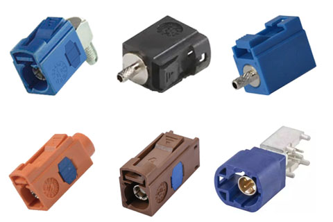
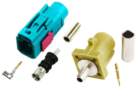
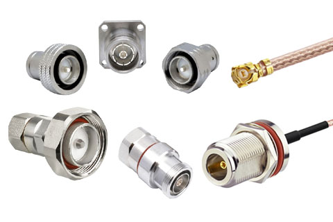
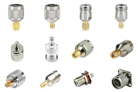
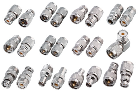
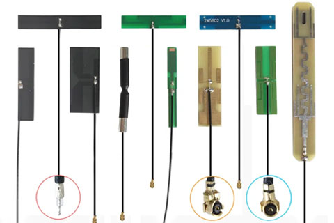
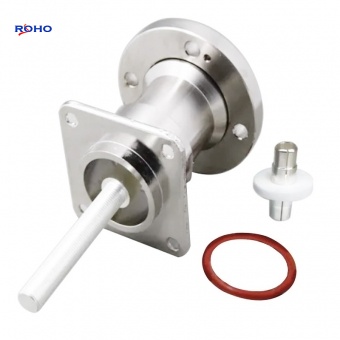
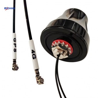
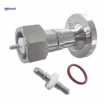
The connector and the binding head, also named as a receptacle, plug, or socket, English name is connector. specifically speaking, The connector is a device used to connect between the circuit conductors, transmission elements,In the two circuit subsystem, The rf connector provide a detachable interface, The interface should not have an unacceptable impact on the performance of the system, The connector here is normally mentioned as electric coupler, A device that connects two active devices. Which is used to transmit current or signals, normally fixed on the Cable (wire)or devices, A detachable device for electrical connection to a transmission system. Electrical connector is a kind of component frequently contacted by electronic engineers, Their function os very simple, In the circuit is blocked or isolated between the circuit, they work as the bridge of communication, so as to make the current flow, the circuit to achieve the intended function. Electrical connectors perform electrical connections and signal transfer between devices and devices, components and systems, It is the basic element necessary to form a complete system, Connector is an indispensable part of electronic equipment. Looking down the current path, you can always find one or more connectors. Connectors vary a lot in forms and structures, With the differences of application object, frequency, power, application environment and other factors, There will be various forms of coaxial connectors, For example: A connector for home wiring, Connectors for lighting on the court, Hard drive connectors, communication networks connectors, Fire the rocket’s connector, Connectors with different requirements and occasions differ greatly in appearance, structure, performance, indexes, etc, But no matter what kind of connector, it is necessary to ensure that the current or signal flowing through it smoothly, continuously and reliably,With the development of science and technology, especially in the rapid development of electronic technology today, Connectors connect to more than just current or simple signals,In optical fiber systems, the carrier of signals is light, and glass and plastic replace the wires in ordinary circuits, It can be transmitted over long distances, optical signal connectors play an important role in long-distance transmission, In China, In the industry management, connectors, switches, keyboards and other components are collectively referred to as electrical connectors, At the same time, electrical connector and relay are collectively referred to as electromechanical components. With the development of consumer electronics, automotive electronics, communication terminal market, China has become the world’s fastest growing connector and the largest capacity market,they are mainly used in transportation, communication, network, IT, medical treatment, home appliances, instruments and meters and other fields...
View details