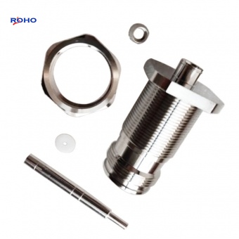
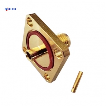
RF BMA connector
Aug 07, 2017
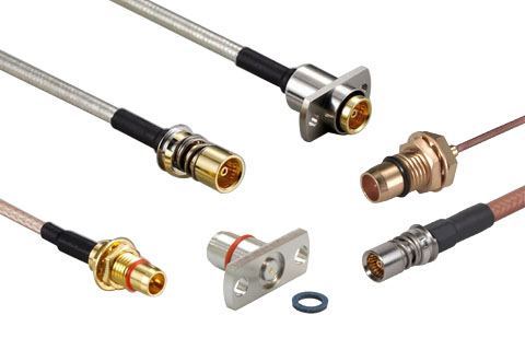
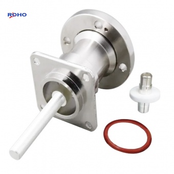
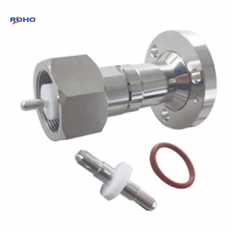
In many applications, screw-on RF connections can sometimes appear stretched and even unusable: for example, panels, daughter cards, or inserts with multiple RF connection points. In these cases, the spacing between the connectors must be set to be very small, so that the nut cannot be accommodated; or the card/combination sometimes cannot be operated due to the need to be inserted into the slot. For these reasons, people have developed push-in connectors, also called blind-mate connectors. The common blind-mate connector in military, aerospace, satellite communications and radar fields is the Blind-mate A/BMA (Blind-mate A/BMA) connector developed in the 1980s. BMA connector In the initial period, the registered trademark used by the BMA connector was OSP, so it is often called OSP connector. The advantage of the BMA connector is that even if there is a slight degree of misalignment, the mating can be easily achieved by pressing the plug into the socket with sufficient pressure, and then the internal mechanical mechanism ensures a firm electrical connection and correct alignment. Thanks to this high-precision alignment method, the operating frequency of the standard BMA connector is as high as 22/26.5 GHz, the voltage standing wave ratio is as low as 1.2:1, and the typical insertion loss is about 0.1dB. In view of the practicality of BMA connectors, people have subsequently developed a variety of alienation styles suitable for different installation types, including BMA coaxial plug/jack connectors, BMA through-wall connectors, BMA panel mount connectors, BMA PCB connectors and screw-in sealed connectors. Generally, the housing and mounting parts of BMA connectors are made of stainless steel or passivated stainless steel, and sometimes gold-plated stainless steel is used. In addition, BMA connectors generally use gold-plated beryllium copper internal contacts and PTFE dielectric materials. Because some BMA connectors have mechanical grooves or mechanical ridges, which help maintain the mating "snap" structure, if there is a sliding-in blind mating connector in the application environment, it will be disconnected due to external force. In the situation, the problem can be solved by using BMA connectors. Since the electrical connection in the BMA connector is achieved through 360-degree contact, it also has a certain degree of vibration resistance and impact resistance. The construction quality and materials used in BMA coaxial connectors allow this type of connector to generally withstand thousands of mating cycles, which is superior to other mechanical retention mechanisms. For measurement test applications and automatic test applications, the BMA connector can be used as a high-reliability connection interface, which not only improves the connection and disconnection speed at the hardware level, but also achieves stronge...
View details