

-
We’re On Call 24/7 : +8613538296050
-
E-mail : anna@rohoconnector.com
We’re On Call 24/7 : +8613538296050
E-mail : anna@rohoconnector.com
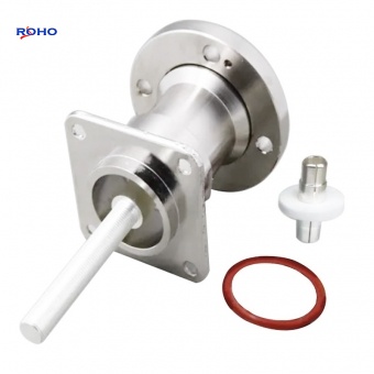
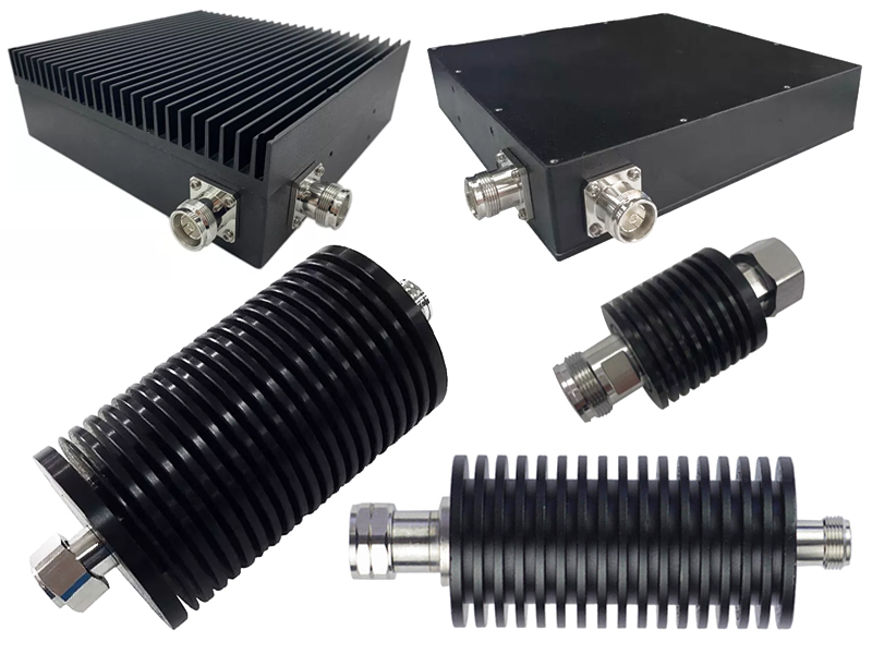
The relentless growth of 5G and the impending dawn of 6G are pushing radio frequency (RF) infrastructure to its limits. In this high-stakes environment, a specific component is gaining prominence for enabling denser, more efficient, and powerful networks: the 4.3-10 Attenuator. Industry leaders like ROHO are at the forefront, driving adoption with a class of fixed attenuators engineered for superior performance in congested signal paths.
Unlike consumer-facing tech, attenuators are often classified by their connector interface and core functionality. The 4.3-10 series stands out as a specialized category designed to meet modern demands.
Connector Interface: The name "4.3-10" itself is a key differentiator. It refers to a compact, lightweight connector interface that offers a superior alternative to traditional 7/16 types, allowing for higher port density in cellular base stations and other space-constrained infrastructure .
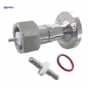
Fixed Attenuation Design: Currently, the 4.3-10 attenuators available on the market are predominantly Fixed Attenuators . This means they provide a single, precise value of signal loss, which is crucial for consistently and predictably setting signal levels in a circuit. Models are available in standard attenuation values such as 3 dB and 10 dB .
Panel Mount Construction: Engineered for robust infrastructure deployment, these attenuators feature a panel mount design . This ensures a secure and stable physical connection, vital for withstanding environmental stress and vibration in outdoor or industrial settings.
The performance profile of 4.3-10 attenuators is tailored for high-power, broadband applications. Key parameters from datasheets highlight their capabilities:
Broad Frequency Operation: These components support a wide frequency range, typically from as low as 100 MHz up to 6000 MHz (6 GHz) . This broad spectrum coverage makes them suitable for a vast array of applications, from legacy systems to modern 5G bands.
Excellent Impedance Matching: A critical parameter for any RF component is the Voltage Standing Wave Ratio (VSWR). A low VSWR indicates good impedance matching and minimal signal reflection. 4.3-10 attenuators maintain a maximum VSWR of 1.4, ensuring efficient power transfer and signal integrity across their operating band .
High Power Handling: A standout feature is their ability to handle significant RF power. With a characteristic impedance of 50 Ω—the standard for most communication systems—these attenuators can manage continuous wave (CW) input power levels exceeding 50 dBm (approximately 100 watts) in some high-power models . This high power tolerance is essential for transmitter stages and power amplifier conditioning.
Ruggedized for Harsh Environments: Built with a metal casing and rated for a wide operating temperature range of -40°C to +40°C , these attenuators are designed to deliver reliable performance in extreme outdoor conditions, from freezing winters to hot summers.
The move towards compact, efficient, and powerful network hardware is unmistakable. The 4.3-10 attenuator, with its optimized interface and robust performance characteristics, is perfectly positioned to be a critical enabler of this transition. As network operators worldwide continue to densify their deployments, the demand for these specialized components is expected to see sustained growth, solidifying their role as a backbone of advanced RF systems.