

-
We’re On Call 24/7 : +8613538296050
-
E-mail : anna@rohoconnector.com
We’re On Call 24/7 : +8613538296050
E-mail : anna@rohoconnector.com
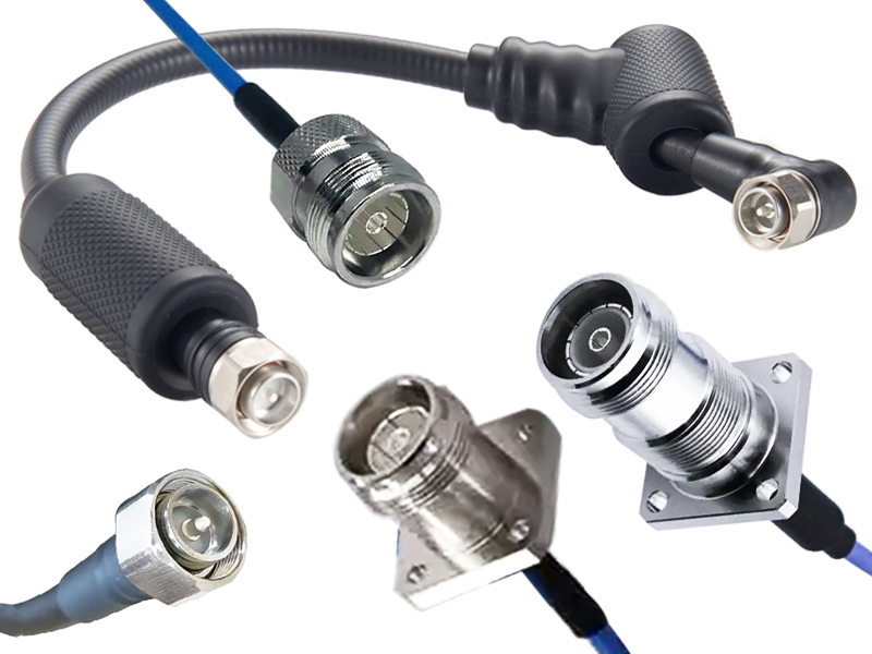
The 4.3-10 connector has rapidly become a preferred interface for modern wireless infrastructure. Standardized under IEC 61169-54, it was developed to replace the larger 7/16 DIN connector in space-constrained base stations while maintaining excellent power handling, low passive intermodulation (PIM), and reliable performance up to 6 GHz. Its compact size, threaded coupling, and weatherproof design make it ideal for macro cells, small cells, distributed antenna systems (DAS), and other dense RF deployments.
One practical question often asked by engineers and installers is: what coaxial cables does a 4.3-10 connector typically terminate? The answer depends on the application—whether it is a short jumper inside an equipment cabinet or a long feeder run up a tower. This guide reviews the most common coaxial cable types used with 4.3-10 connectors, without reference to any specific manufacturer.
Impedance: 50 Ω Only
Before discussing cable types, it is important to note that 4.3-10 connectors are designed almost exclusively for 50 Ω systems. This is the standard impedance for cellular infrastructure, wireless communications, and RF test equipment. Unlike some connector families that offer both 50 Ω and 75 Ω versions, the 4.3-10 interface is not commonly produced in 75 Ω. Therefore, all compatible coaxial cables must be 50 Ω.
Using a 75 Ω cable with a 4.3-10 connector would introduce a severe impedance mismatch, causing high VSWR, signal reflections, and degraded system performance. Always verify the cable's impedance before termination.
Common Coaxial Cable Types for 4.3-10 Connectors
4.3-10 connectors are available with different cable attachment styles—clamp, crimp, and solder—to accommodate a range of cable diameters and constructions. The following cable families are most commonly paired with 4.3-10 connectors.
1. Flexible Low-Loss Cables (RG-Series)
Several traditional RG-style cables remain widely used with 4.3-10 connectors, particularly for indoor jumpers, short interconnects, and lower-power applications.
| Cable Type | Typical Applications | Key Characteristics |
| RG-213/U | Base station jumpers, general RF interconnects | Large diameter, low loss, rugged, widely available |
| RG-214/U | High-power, interference-prone environments | Double-shielded version of RG-213, excellent shielding |
| RG-393/U | Military, aerospace, high-reliability systems | High-temperature, low-loss, rugged construction |
| RG-8/U | Amateur radio, legacy infrastructure | Large diameter, moderate loss, time-tested |
| RG-8X | Compact installations, short runs | Smaller version of RG-8, flexible |
| RG-58/U | Low-power test leads, short jumpers | Very flexible, small diameter, higher loss |
| RG-400/U | High-reliability test and aerospace | Double-shielded, low-loss, high-temperature |
These cables are typically used for shorter runs where flexibility and ease of installation are more important than absolute minimum loss.
2. Foam-Dielectric Flexible Cables (1/2-Inch Class)
The most common cable type for 4.3-10 connectors in cellular infrastructure is 1/2-inch foam-dielectric coaxial cable. This cable offers an excellent balance of low loss, flexibility, and power handling, making it ideal for jumper connections between remote radio heads (RRHs) and antennas, as well as short feeder runs.
Common generic descriptions include:
1/2-inch foam dielectric coaxial cable
1/2-inch low-loss flexible cable
These cables are available in standard and low-PIM versions. For multi-carrier cellular sites, low-PIM cable is essential to prevent interference. The 4.3-10 connector is frequently specified with this cable class because it matches the connector's compact size and power rating.
3. Corrugated Copper Cables (7/8-Inch and Larger)
For longer feeder runs—such as from the base of a tower to the antenna—corrugated copper coaxial cables are used. These cables have a corrugated outer conductor, which provides excellent flexibility, low loss, and high power handling. Common sizes include:
| Cable Size | Typical Applications | Key Characteristics |
| 7/8-inch corrugated | Main tower feeder runs, medium-length transmission | Low loss, good flexibility, high power |
| 1-1/4-inch corrugated | Long feeder runs, high-power macro cells | Very low loss, higher power handling |
| 1-5/8-inch corrugated | Very long runs, broadcast, high-power systems | Ultra-low loss, maximum power handling |
4.3-10 connectors are commonly used on 7/8-inch corrugated cable, especially in modern macro-cell deployments where the compact connector helps reduce tower loading and installation time. Adapters or jumper assemblies are often used to transition between the 7/8-inch feeder and the 1/2-inch jumper at the antenna.
4. Air-Dielectric Cables
For specialized high-power and low-loss applications, air-dielectric coaxial cables may be terminated with 4.3-10 connectors. These cables use air as the primary dielectric, resulting in extremely low loss but requiring careful pressurization or sealing to prevent moisture ingress. They are less common in typical cellular deployments but may appear in broadcast or high-power radar systems.
5. Semi-Rigid and Conformable Cables
In some test and measurement or military applications, 4.3-10 connectors may be used with semi-rigid or conformable coaxial cables. These cables offer excellent shielding, phase stability, and low loss but are less flexible and require special bending tools. They are not typical for outdoor infrastructure but may be found in equipment racks or test benches.
6. Low-PIM Specialty Cables
For multi-carrier, multi-operator cellular systems, low-PIM coaxial cables are increasingly used with 4.3-10 connectors. These cables are designed with non-ferromagnetic materials, precise impedance control, and high-quality shielding to minimize passive intermodulation. They are available in both 1/2-inch flexible and 7/8-inch corrugated constructions.
Summary of Common Cable Pairings
| Cable Category | Typical Size / Type | Common Applications | Key Benefits |
| RG-213/U, RG-214/U | Flexible, ~10 mm diameter | Jumpers, indoor interconnects | Low cost, widely available |
| RG-393/U, RG-400/U | Flexible, high-reliability | Military, aerospace, test | High temperature, low loss |
| 1/2-inch foam dielectric | Flexible, low-loss | RRH-to-antenna jumpers, DAS | Excellent balance of loss and flexibility |
| 7/8-inch corrugated | Semi-flexible, corrugated | Tower feeder runs | Low loss, high power, rugged |
| 1-1/4-inch corrugated | Semi-flexible, corrugated | Long feeder runs | Very low loss, high power |
| 1-5/8-inch corrugated | Semi-flexible, corrugated | Broadcast, very long runs | Ultra-low loss, maximum power |
| Air-dielectric | Rigid or semi-rigid | High-power broadcast, radar | Lowest loss, highest power |
| Semi-rigid / conformable | Solid or conformable shield | Test, military, phase-critical | Excellent shielding, phase stability |
Selection Considerations
When choosing a coaxial cable for a 4.3-10 connector, consider the following factors:
| Factor | Considerations |
| Frequency range | 4.3-10 connectors operate up to 6 GHz. Ensure the cable's loss is acceptable at your highest frequency. |
| Power handling | Larger cables (7/8-inch and above) handle more power; 1/2-inch cables are suitable for moderate power. |
| Attenuation / Loss | For long runs, choose 7/8-inch or larger corrugated cable. For short jumpers, 1/2-inch foam or RG-213 is adequate. |
| PIM performance | For multi-carrier cellular sites, specify low-PIM cable and connectors. |
| Flexibility and bend radius | 1/2-inch foam cable is flexible; 7/8-inch corrugated is semi-flexible; 1-5/8-inch is stiff. |
| Environmental conditions | Outdoor cables need UV-resistant, water-blocking jackets and weatherproof connectors. |
| Connector attachment | Ensure the 4.3-10 connector is designed for the specific cable diameter and construction (clamp, crimp, or solder). |
| Cost | RG-213 is economical; 1/2-inch foam is moderate; 7/8-inch corrugated is higher; air-dielectric is premium. |
Installation Best Practices
To achieve the best performance from a 4.3-10 connector and cable assembly:
Use the correct stripping tools: Each cable type requires specific strip lengths. Follow the connector manufacturer's instructions.
Maintain proper torque: 4.3-10 connectors typically require 1.0–1.5 Nm of torque. Over-torquing can damage threads; under-torquing can cause PIM and signal loss.
Keep connectors clean: Contamination is a leading cause of high PIM. Clean mating surfaces with isopropyl alcohol before connection.
Weatherproof outdoor connections: Use self-amalgamating tape and mastic to seal the connector-cable junction.
Support the cable: Avoid placing mechanical stress on the connector. Use cable ties and hangers at recommended intervals.
Test after installation: Verify VSWR and, for cellular sites, PIM performance to ensure the assembly meets specifications.
Conclusion
The 4.3-10 connector is a compact, high-performance interface that has become a standard in modern wireless infrastructure. It is most commonly terminated on 1/2-inch foam-dielectric flexible cable for jumpers and on 7/8-inch corrugated copper cable for tower feeder runs. Other compatible cables include RG-213/U, RG-214/U, RG-393/U, RG-400/U, larger corrugated cables (1-1/4-inch and 1-5/8-inch), and specialized air-dielectric or low-PIM cables.
When selecting a cable for a 4.3-10 connector, always verify 50 Ω impedance, frequency range, power handling, PIM performance, and environmental suitability. With the right cable and proper installation, a 4.3-10 connector assembly will deliver reliable, low-loss, and interference-free performance for years of service in the most demanding RF environments.